Magnetic bearing based on radial rejection and application thereof

A magnetic bearing and radial magnetic field technology, applied in the field of magnetic bearings, can solve the problems of dynamic unbalance, high-speed collision, difficult system control, etc., and achieve the effects of being beneficial to storage, simple and compact in structure, and high in efficiency.

Inactive Publication Date: 2013-07-24
ZHEJIANG UNIV
View PDF3 Cites 4 Cited by
  • Summary
  • Abstract
  • Description
  • Claims
  • Application Information

AI Technical Summary

Problems solved by technology

In the traditional flywheel energy storage system based on electromagnetic suspension bearings, the suspension of the main shaft is realized through electromagnetic bearings composed of drivers, sensors and control systems. Two sets of radial electromagnetic bearings are used to realize the suspension of four degrees of freedom in the radial direction of the main shaft of the flywheel; since the electromagnetic bearing and the casing are respectively magnetic objects and magnetic materials, there will be mutual attraction between the two, and the The attractive force will become bigger and bigger as the distance between the two gets closer, so the whole open-loop system is a dynamic unbalanced system, which makes it difficult to control the whole system
[0005] In addition, the electromagnetic bearing flywheel energy storage system widely researched and invented at home and abroad is mostly controlled by feedback closed-loop system, PI control or other control methods. In a flywheel energy storage system with high-speed rotation and large moment of inertia, The above-mentioned defects are difficult to solve through the feedback closed-loop system, which will cause great harm to the entire flywheel energy storage system, such as high-speed collision between the casing and the main shaft, etc.

Method used


Image

  • Magnetic bearing based on radial rejection and application thereof
  • Magnetic bearing based on radial rejection and application thereof
  • Magnetic bearing based on radial rejection and application thereof

Examples


Embodiment Construction

[0024] In order to describe the present invention more specifically, the technical solutions of the present invention will be described in detail below in conjunction with the accompanying drawings and specific embodiments.

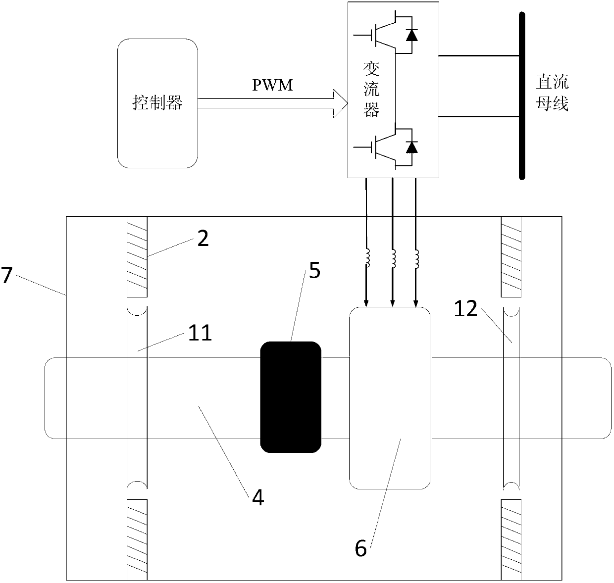
[0025] Such as figure 1 As shown, a flywheel energy storage device includes: a main shaft 4, a converter, a controller and a casing 7; the main shaft 4 is arranged in the casing 7, and a first magnetic bearing 11, a flywheel 5, The motor 6 and the second magnetic bearing 12 are provided with a plurality of iron cores 2 inside the casing 7; wherein:

[0026] The motor 6 adopts a permanent magnet synchronous motor, which includes a rotor and a stator; the rotor is mounted on the main shaft 4 and has two pairs of poles, the permanent magnets of the rotor are arranged with the same polarity in the radial direction, and the rotor cores between the permanent magnets are alternately Magnetized to the same polarity; the stator has three-phase windings, and each ...


PUM


Abstract

The invention discloses a magnetic bearing based on radial rejection. The magnetic bearing comprises an annular permanent magnet; 2n current coils are evenly arranged around the annular permanent magnet along a radial direction; and the direction of radial magnetic field generated by the annular permanent magnet is opposite to the direction of radial magnetic field generated by the electric coils. The magnetic bearing employs interaction of the annular permanent magnet and the winding coils to produce radial suspension repulsion; and the magnetic bearing device has simple and compact structure, and is stable and reliable. The invention also discloses a flywheel energy storing device applying the magnetic bearing device; the energy storing device employs exclusive principle of magnetic fields with the same polarity to form a dynamically stable system; and closer distance generates stronger repulsion, so as to facilitate high speed operation of the spindle without colliding or scraping with inner wall of the casing.

Description

technical field [0001] The invention belongs to the technical field of magnetic bearings, and in particular relates to a magnetic bearing based on radial repulsion and its application. Background technique [0002] Electromagnetic bearing is a high-tech mechatronic product with no physical contact, which is the most important feature of its application. Since there is no physical contact, there is no friction, so the electromagnetic bearing has the characteristics of no friction and wear, high speed, no need for lubrication, and long life. These advantages are difficult to achieve with ordinary mechanical bearings. Electromagnetic bearings are mainly used in occasions requiring high speed, high power, high precision and high efficiency. [0003] Flywheel energy storage technology uses a high-speed rotating flywheel as a carrier, converts electrical energy into mechanical energy and stores it in the high-speed rotating flywheel, and realizes the storage and release of electr...

Claims


Application Information

Patent Timeline
Patent Type & Authority Applications(China)
IPC IPC(8): F16C32/04H02K7/02
CPCY02E60/16
Inventor 杨家强彭丹
Owner ZHEJIANG UNIV
Why Eureka
Try Eureka