Eureka AIR delivers breakthrough ideas for toughest innovation challenges, trusted by R&D personnel around the world.

Brake device

A brake device and brake oil technology, which is applied in the direction of brake actuators, gear transmission mechanisms, mechanical equipment, etc., can solve the problems of incomplete separation between brake pads and wheel hubs, short service life of brake devices, and affecting vehicle driving conditions. Achieve the effects of reduced driving load, increased service life and high reliability

Inactive Publication Date: 2015-06-10
张庆冬
View PDF6 Cites 0 Cited by
  • Summary
  • Abstract
  • Description
  • Claims
  • Application Information

AI Technical Summary

Problems solved by technology

[0003] The problem to be solved by the present invention is to provide a brake device, which can solve the problem that the brake pads and the wheel hub are not completely separated when the brake is released in the existing brake device, and the brake is not sensitive, which affects the driving condition of the vehicle, the driving load, and the service life of the brake device. short question

Method used


Image

  • Brake device
  • Brake device
  • Brake device

Examples


Embodiment Construction

[0019] Embodiments of the present invention are described in further detail below in conjunction with the accompanying drawings:

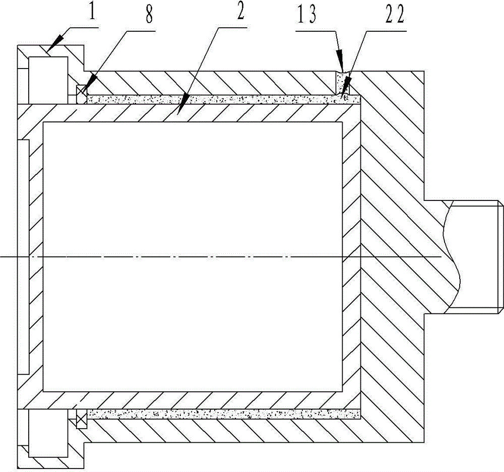
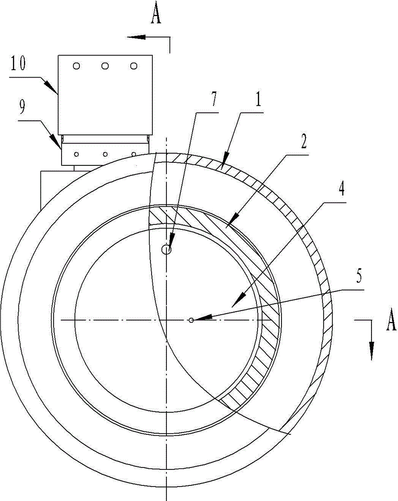
[0020] Such as Figure 2 to Figure 7 The brake device shown includes a housing 1 with a brake oil hole 13 and a piston 2 installed in the housing 1 through a piston oil seal ring 8. One end of the piston 2 is provided with a through hole, and the end of the through hole faces the housing. The sealing end of the body 1, the inner cavity of the piston 2 is set with the inner piston 4 through the inner piston oil seal ring 3, and the inner piston 2 inner cavity is divided into the brake oil chamber 6 and the lubricating oil chamber 20 by the inner piston oil seal ring 3, and the inner piston oil seal The space between the ring 3 and the piston 2 forms a brake oil chamber 6; one end of the inner piston 4 protrudes and is fixed from the through hole of the piston 2 and the hole 14 of the sealing end of the housing 1, and the brake oil hole 13 of the hou...


PUM


Abstract

The invention discloses a brake device which comprises a shell and a piston, the shell is provided with a brake oil hole, and the piston is installed in the shell through piston oil sealing rings. A through hole is formed at one end of the piston, the through hole faces toward the sealing end of the shell, an inner piston is installed in an inner cavity of the piston in a sleeved mode through an inner piston oil sealing ring. The inner cavity of the piston is divided into a brake oil chamber and a lubricating oil chamber by the inner piston oil sealing ring. One end of the inner piston extends out of the through hole in the piston and a hole in the sealing end of the shell to be fixed. The brake oil hole in the shell is communicated with a brake oil way in the shell, an oil inlet duct is arranged in the inner piston and communicated with the brake oil way, and an oil outlet of the oil inlet duct is communicated with the brake oil chamber. An oil-control device is arranged outside the shell, and an oil duct is communicated with the inner cavity of the shell. The problems that at the time of braking, a brake pad and a wheel hub are not separated completely, driving conditions of a vehicle are influenced, and service life of a brake device is short can be solved.

Description

technical field [0001] The invention relates to the technical field of auto parts, in particular to a device installed between an automobile brake pad and a transmission mechanism for driving the brake pad to be released or locked. Background technique [0002] Existing brake devices generally control the piston in the housing to extend in and out through the brake fluid in and out of the housing, and the movement of the piston relative to the housing makes the brake pads driven by the outer end of the piston compress or loosen the hub of the automobile wheel. To play a role in controlling the brakes. Its structure is generally a cylindrical shell with an opening at one end, and a piston 2 is installed through a rubber piston seal oil ring 8, such as figure 1 As shown, the outer end surface of the piston 2 is connected to the brake pad, and the housing 1 is connected to the power transmission device and the brake oil circuit of the vehicle. The gap between the inner walls,...

Claims


Application Information

Patent Timeline
Patent Type & Authority Patents(China)
IPC IPC(8): F16D65/14F16D121/04F16D125/06
Inventor 张庆冬
Owner 张庆冬
Why Eureka
Eureka Blog
Learn More