Electro-acoustic transducer and manufacturing method thereof

An electro-acoustic transducer and manufacturing method technology, applied in the direction of sensors, electrical components, etc., capable of solving problems such as danger of use

Active Publication Date: 2013-07-24
亿客来国际有限公司
View PDF6 Cites 4 Cited by
  • Summary
  • Abstract
  • Description
  • Claims
  • Application Information

AI Technical Summary

Problems solved by technology

However, excessive voltage may cause danger in the use of

Method used


Image

  • Electro-acoustic transducer and manufacturing method thereof
  • Electro-acoustic transducer and manufacturing method thereof
  • Electro-acoustic transducer and manufacturing method thereof

Examples


Embodiment Construction

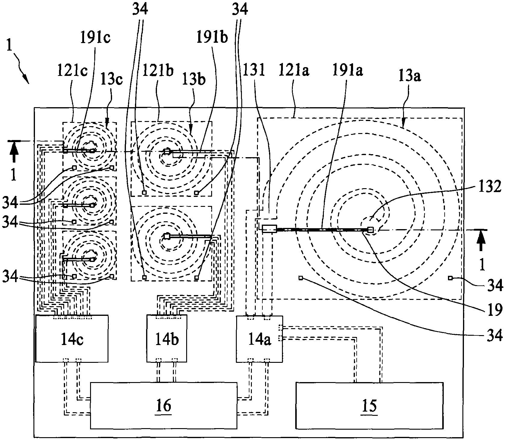
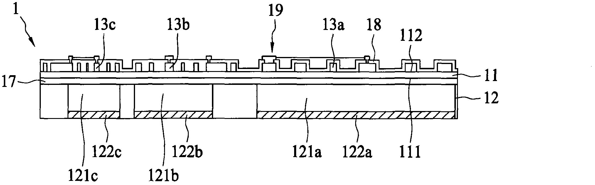
[0047] figure 1 A schematic top view of an electro-acoustic transducer 1 according to an embodiment of the present invention is shown. figure 2 for along figure 1 Sectional view of the 1-1 section line. refer to figure 1 and figure 2 As shown, the electro-acoustic transducer 1 may include an insulating flexible substrate 11, a base 12, and at least one magnetic field generator (13a, 13b or 13c). The base 12 may have at least one cavity (121a, 121b or 121c) and at least one magnetic portion (122a, 122b or 122c), wherein at least one magnetic portion (122a, 122b or 122c) is correspondingly formed in the at least one cavity (121a, 121b or under 121c), as in figure 1 shown. The insulating flexible substrate 11 is disposed on the base 12, covering at least one cavity (121a, 121b or 121c), so that the insulating flexible substrate 11 can be supported, and at least one cavity (121a, 121b or 121c), there can be a space to generate vibration. At least one magnetic field gener...


PUM


Abstract

The invention relates to an electro-acoustic transducer and a manufacturing method of the electro-acoustic transducer. The electro-acoustic transducer comprises an insulating flexible substrate, a substrate, and a magnetic field generating device, wherein the substrate comprises a hollow cavity and a magnetic portion, and the magnetic portion can be located under the hollow cavity. The insulating flexible substrate can cover the hollow cavity. The magnetic field generating device can be arranged on the insulating flexible substrate and corresponds to the hollow cavity. The magnetic field generating device can generate a magnetic field and a reversed magnetic field, the magnetic field and the reversed magnetic field can act with the magnetic portion, the magnetic field and the magnetic portion of the substrate can generate attractive interaction or repulsive interaction, and therefore the insulating flexible substrate generates vibrations.

Description

technical field [0001] The present invention relates to an electroacoustic transducer and a manufacturing method thereof, in particular to an electroacoustic transducer of a loudspeaker and a manufacturing method thereof. Background technique [0002] A flexible ultra-thin speaker (or called a paper speaker or an electrostatic speaker) has a first electrode, a second electrode, and a vibrating metal film with a positive charge sandwiched between the first and second electrodes. When the first electrode is positively charged and the second electrode is negatively charged, the metal film will be far away from the first electrode and close to the second electrode; and when the first electrode is negatively charged and the second electrode is positively charged, The metal film is close to the first electrode and far away from the second electrode. Constantly changing the electrical properties of the charges on the first electrode and the second electrode can make the metal film...

Claims


Application Information

Patent Timeline
Patent Type & Authority Applications(China)
IPC IPC(8): H04R9/06H04R9/02H04R31/00
Inventor 林君明
Owner 亿客来国际有限公司
Why Eureka
Try Eureka