Earphone with passive radiator

a passive radiator and earphone technology, applied in the field of earphones, can solve the problems of limited resonance and bass drop sound effects, limited application of conventional passive radiators to large speakers without being seen in earphones, etc., and achieve the effect of optimizing audio performance and enhancing the resonance effect of the back cavity

Inactive Publication Date: 2016-07-26
MERRY ELECTRONICS (SHENZHEN) CO LTD
View PDF3 Cites 3 Cited by
  • Summary
  • Abstract
  • Description
  • Claims
  • Application Information

AI Technical Summary

Benefits of technology

[0006]The present invention has been accomplished under the circumstances in view. It is the main object of the present invention to provide an earphone, which enhances the resonance effect of the back cavity and optimizing audio performance.
[0007]It is another object of the present invention to provide an earphone, which has a passive radiator built therein, enabling a weight in the passive radiator to be firmly connected with the vibrating diaphragm.
[0010]Subject to the mounting arrangement of the passive radiator, the sound performance of the earphone is optimized, and the weight of the passive radiator is firmly connected with the vibrating diaphragm main body. Even if the vibrating diaphragm main body vibrates heavily, the weight will not fall.

Problems solved by technology

However, the applications of conventional passive radiators are mostly limited to large speakers without being seen in earphones.
The back cavity of an earphone is relatively smaller, so its resonance and bass drop sound effects are limited.

Method used


Image

  • Earphone with passive radiator
  • Earphone with passive radiator
  • Earphone with passive radiator

Examples


first embodiment

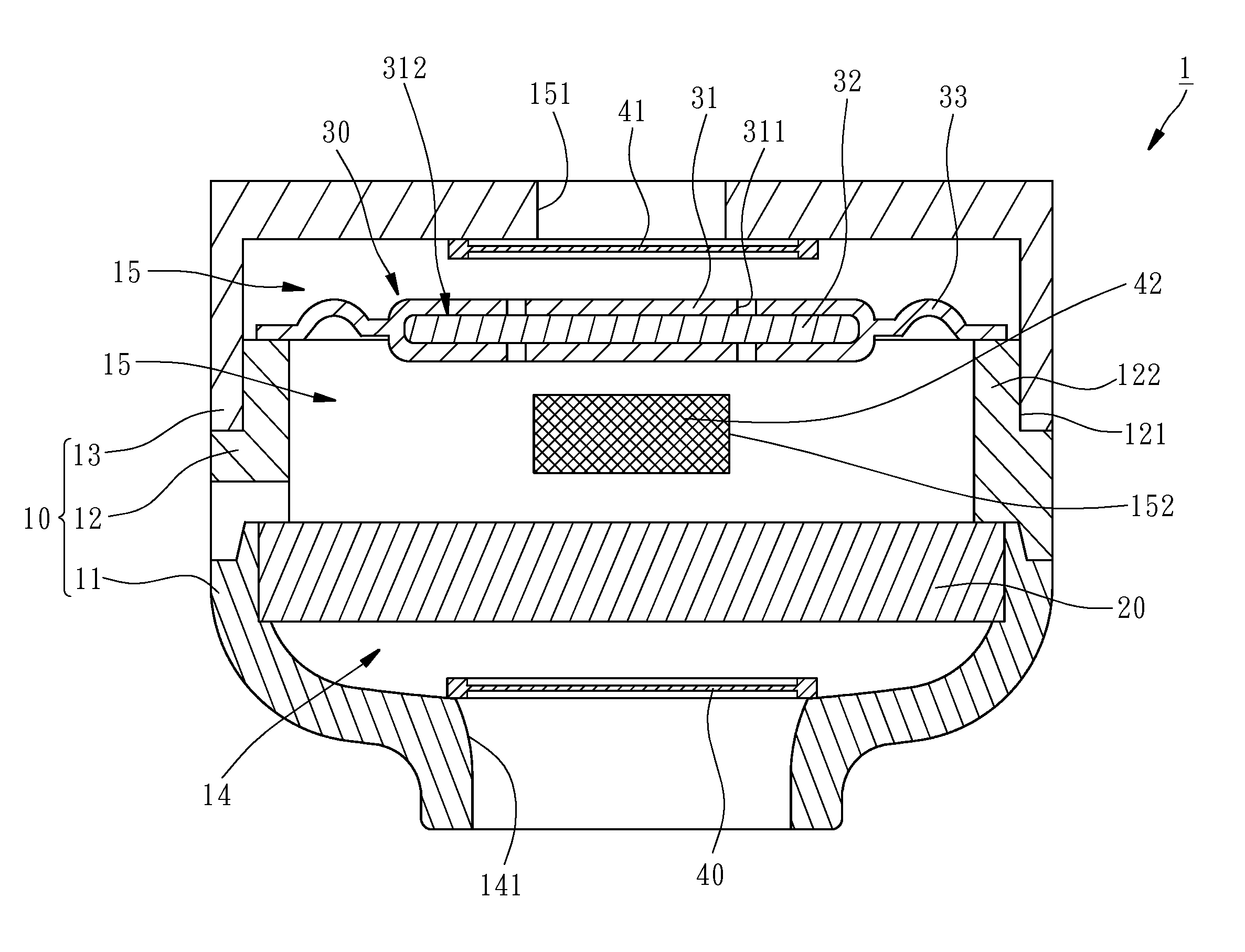
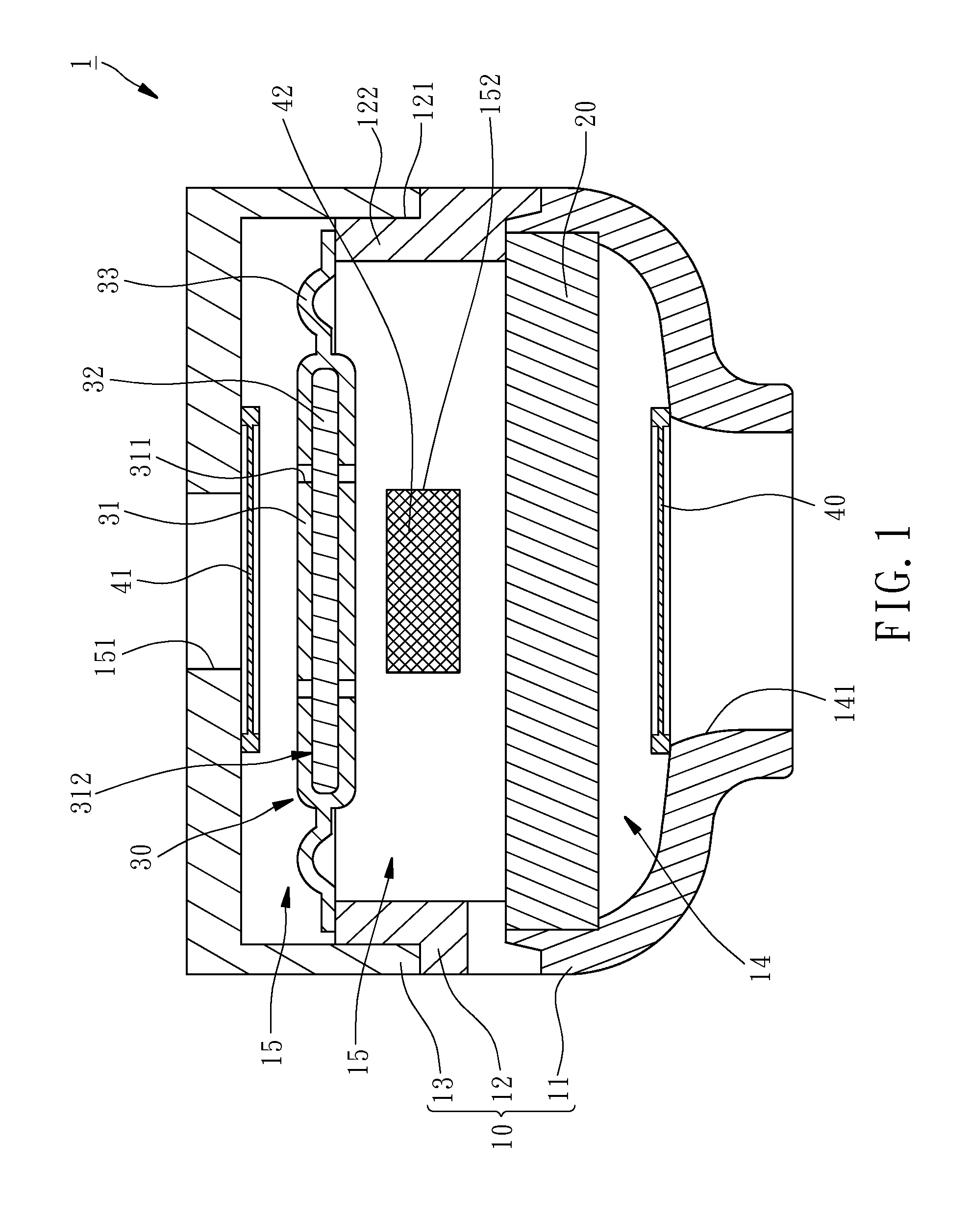
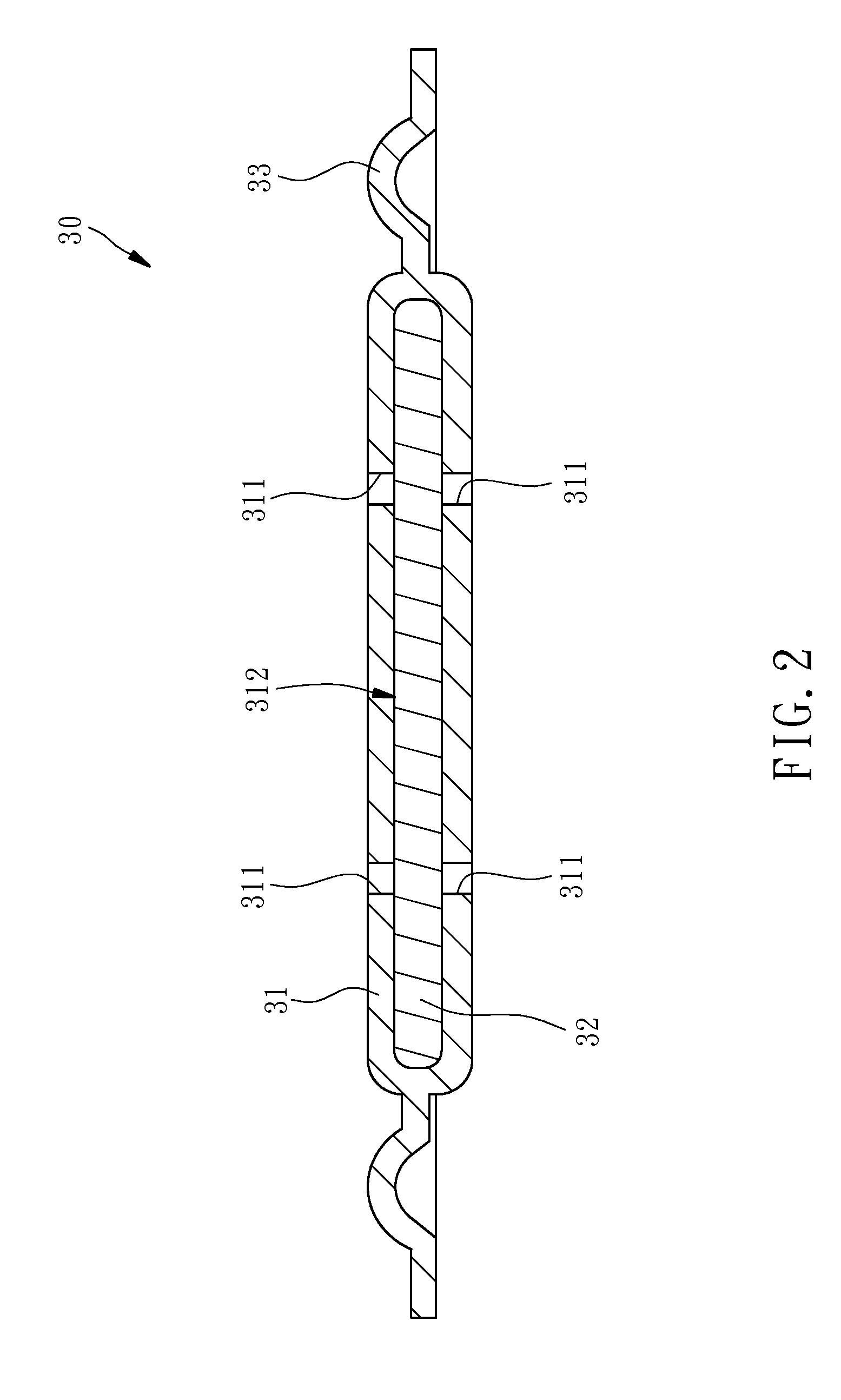
[0018]For easily understanding the structural details and features of the present invention, an earphone 1 in accordance with a first embodiment is provided and illustrated in FIGS. 1 and 2. As illustrated, the earphone 1 comprises a housing 10, a speaker 20, and a passive radiator 30. The structural details of these component parts and their relative relationship are explained hereinafter.

[0019]Referring to FIG. 1 again, the housing 10 is a hollow member comprised of a first outer shell 11, a second outer shell 12 and an outer cover 13. The second outer shell 12 is press-fitted onto the first outer shell 11, comprising an annular groove 121 and an inner flange 122 located at one side thereof remote from the first outer shell 11. The outer cover 13 is fastened to the annular groove 121 of the second outer shell 12.

[0020]The speaker 20 is fixedly mounted in the first outer shell 11 of the housing 10 to divide the internal space of the housing 10 into a first cavity 14 and a second ca...

second embodiment

[0028]Further, injection molding technology can also be used for the fabrication of the passive radiator 50 in this During fabrication, put the weight 80 in the mold, and then mold the first composite layer 61 and the second composite layer 62 on the passive radiator 50, either in a proper order or at the same time, using injection molding technology. Thus, the weight 80 will not fall out of the vibrating diaphragm main body 60 easily. Whether using the technique of press forming or injection molding, these two methods can easily allocate the weight 80, and simplify mass fabrication of the passive radiator 50.

[0029]Referring to FIG. 4, an earphone in accordance with a third embodiment of the present invention is shown. This third embodiment is substantially similar to the aforesaid first embodiment with the exception that the weight 80 of the passive radiator 50 in this third embodiment is bonded to the top surface of the vibrating diaphragm main body 60. However, this top mounting...


PUM


Abstract

An earphone includes a housing having a sound-emitting hole, a speaker mounted in the housing, and a passive radiator mounted in between the sound hole and the speaker driver and including a vibrating diaphragm main body and a weight embedded in the vibrating diaphragm main body or bonded to the top or bottom surface of the vibrating diaphragm main body. The mounting arrangement of the passive radiator optimizes the sound performance of the earphone. The weight of the passive radiator is firmly connected with the vibrating diaphragm main body so that severe vibration of the vibrating diaphragm main body does not cause disconnection of the weight.

Description

BACKGROUND OF THE INVENTION[0001]1. Field of the Invention[0002]The present invention relates to earphone technology, and more particularly, to an earphone having a passive radiator therein.[0003]2. Description of the Related Art[0004]Passive vibration diaphragm, also called as passive radiator, is normally mounted with a speaker in a cabinet to share the back cavity so that when the speaker converts electrical energy to sound waves, the air in the back cavity is compressed and transferred to the passive radiator, thereby indirectly driving the passive radiator to emit sound waves. Subject to the assistance of a passive radiator in a miniature speaker, the resonance effect of the back cavity is enhanced, and the overall performance of the sound field is optimized.[0005]However, the applications of conventional passive radiators are mostly limited to large speakers without being seen in earphones. The back cavity of an earphone is relatively smaller, so its resonance and bass drop so...

Claims


Application Information

Patent Timeline
Patent Type & Authority Patents(United States)
IPC IPC(8): H04R1/20H04R1/28H04R1/10
CPCH04R1/1058H04R1/1091H04R1/283H04R1/2834H04R1/2849H04R2231/003
Inventor YEH, RUEI-TING
Owner MERRY ELECTRONICS (SHENZHEN) CO LTD
Why Eureka
Try Eureka