
Friction stir welding device

A welding device and friction stir technology are applied in the field of aluminum and aluminum alloy welding, which can solve the problems of pipe weld strength defects, affecting the use range of pipes, and reducing weld strength, etc., and achieve excellent mechanical properties, grain refinement, and improvement. the effect of strength

Active Publication Date: 2016-04-13
姚雪飞
View PDF10 Cites 0 Cited by
  • Summary
  • Abstract
  • Description
  • Claims
  • Application Information

AI Technical Summary

Problems solved by technology

This causes the strength of the weld area to be lower than the strength of the base metal area of ​​the spiral pipe, making the pipe have weld strength defects
However, this type of spiral welded pipe is widely used in various industries, and the reduction in the strength of the weld will greatly affect the scope of use of this type of pipe.

Method used


Image

  • Friction stir welding device
  • Friction stir welding device
  • Friction stir welding device

Examples


Embodiment Construction

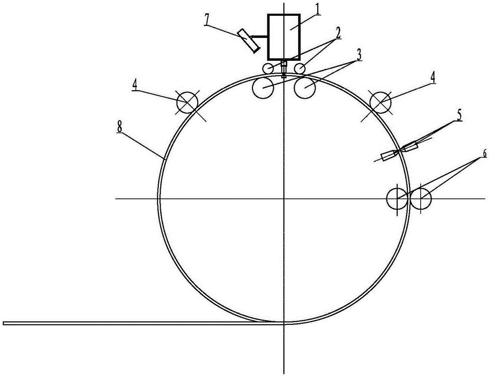
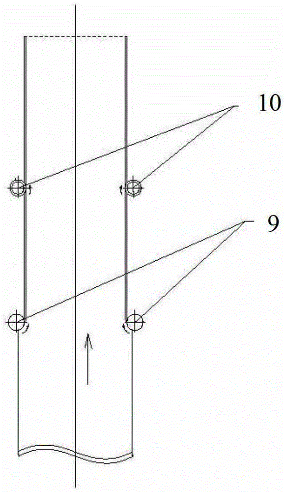
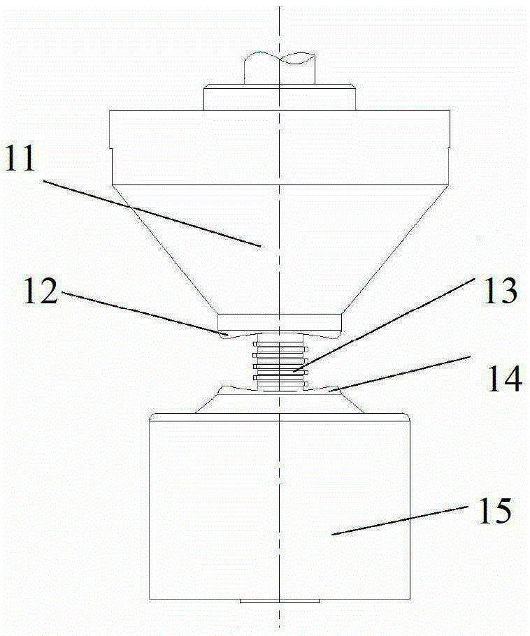
[0018] The present invention will be described in further detail below, so that those skilled in the art can implement it with reference to the description. figure 1 is a sectional view of a preferred embodiment of the friction stir welding apparatus according to the present invention. figure 2 It is a schematic diagram of the pressure roller of the stirring head of the friction stir welding equipment according to the present invention. image 3 It is a schematic diagram of the stirring head of the friction stir welding equipment according to the present invention. Such as figure 1 , figure 2 , image 3 As shown, the friction stir welding device includes: a high-speed motor (not shown); a stirring head 1, which is connected to the output shaft of the high-speed motor, including a stirring pin 13 and two shoulders 11, 15, two The surfaces 12 and 14 of the shaft shoulder contacting the weldment are arc-shaped support fans; when the friction stir welding equipment is used f...


PUM


Abstract

The invention discloses a stirring and friction welding device which mainly comprises a high-speed motor, a stirring head connected onto the output shaft of the high-speed motor, as well as a stirring pin and two shaft shoulders, and the contacting surface between the two shaft shoulders and the weld assembly is of an arc supporting sector. According to the stirring, friction and welding device provided by the invention, the welding seam height is increased, and the welding seam intensity is improved as well.

Description

technical field [0001] The invention relates to the field of aluminum and aluminum alloy welding, in particular to a friction stir welding device. Background technique [0002] Aluminum and aluminum alloy spiral tubes are made by rolling aluminum and aluminum alloy coils into tube blanks at a certain helical angle, and then welding the tube seams. Pipes with different diameters and specifications can be produced by continuous crimping and welding of coils of one width. This kind of pipes is widely used in electrical, petrochemical and low-temperature storage tanks and other fields. When friction stir welding is used to produce aluminum and aluminum alloy spiral tubes, there is no newly added base metal, such as welding wire, in the welding area of ​​the spiral tubes. Therefore, the weld height did not increase, but decreased slightly. This causes the strength of the weld area to be lower than the strength of the metal area of ​​the spiral tube base, making the pipe have we...

Claims


Application Information

Patent Timeline
Patent Type & Authority Patents(China)
IPC IPC(8): B23K20/12B23K20/26
Inventor 姚雪飞
Owner 姚雪飞
Learn More