Multi-layer oil guide clapboard of hydraulic oil press

A technology of hydraulic oil extraction and partitions, which is applied to presses, manufacturing tools, etc., which can solve the problems of slow oil output, no oil coming out of oil cakes, and low output, and achieve fast oil output, high oil output rate, The effect of increasing yield

Inactive Publication Date: 2013-07-31
刘跃
View PDF5 Cites 0 Cited by
  • Summary
  • Abstract
  • Description
  • Claims
  • Application Information

AI Technical Summary

Problems solved by technology

[0003] The technical problem to be solved by the present invention is to solve the problems in the prior art that the oil does not come out in the middle of the oil cake, the oil output is too slow, and the output is low, that is, the horizontal oil output of the oil cake in the original technology is changed to the vertical direction after being pressed. Oil outlet, providing a hydraulic oil press multi-layer oil guide separator with shortened oil outlet channel, fast oil outlet, high oil outlet rate and increased output

Method used


Image

  • Multi-layer oil guide clapboard of hydraulic oil press
  • Multi-layer oil guide clapboard of hydraulic oil press
  • Multi-layer oil guide clapboard of hydraulic oil press

Examples


Embodiment 1

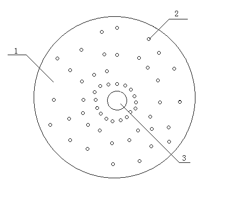
[0019] A multi-layer oil-guiding baffle for a hydraulic oil press according to the present invention is a groove on one side of the baffle 1 with a diameter of 100 mm and a thickness of 1 mm, which is connected with the oil outlet holes 2 radially from the center of the baffle 1 to the edge and leads to the edge of the oil cake. There are 16 oil guide grooves 4 with a depth of 0.5 mm and a groove width of 1 mm, which are oil passages. Drill from the center to the edge along each oil guide groove 4 on the separator 1 6 diameter 0.2 mm oil hole 2. When in use, the side of each layer of partitions 1 that does not open the oil passage faces the oil cake, and two partitions 1 are placed on the same position and one layer at the same time, and a layer of steel wire mesh is placed in the center of the two partitions 1. The rest of the operation is the same as that of the original hydraulic press. The oil machine uses the same. When the oil press presses down, the oil squeezed ou...

Embodiment 2

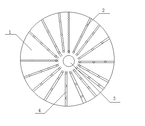
[0021] A kind of multi-layer oil-guiding separator for a hydraulic oil press of the present invention is a groove with a depth of 1.5mm and a groove width of 2mm that is parallel to the center line of the separator 1 and communicates with the oil outlet 2 on one side of the separator 1 with a diameter of 1000 mm and a thickness of 3 mm. There are 11 oil guide grooves 4 in total, i.e. oil passages; 6-50 diameter 3mm oil outlet holes 2 are drilled in each oil guide groove 4 on the dividing plate 1. When in use, the side of each layer of partitions 1 without the oil guide groove 4 is facing the oil cake. Two partitions 1 are placed on the same position and one layer at the same time, and a layer of steel wire mesh is placed in the center of the two partitions 1. The rest of the operation is the same as that of the original hydraulic oil press. The machine uses the same. When the oil extractor rod is pressed downward, the oil extracted from the oil plant will seep out along the ed...

Embodiment 3

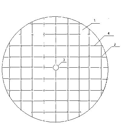
[0023] A multi-layer oil-conducting separator for a hydraulic oil press of the present invention is formed on one side of the separator 1 with a diameter of 2000 mm and a thickness of 5. There are 11 connected oil guide grooves 4 with a depth of 3mm and a width of 3mm respectively, that is, oil passages. Drill 6-50 oil outlet holes 2 with a diameter of 5mm in each oil guide groove 4 on the separator 1. When in use, the side of each layer of separator 1 that does not open the oil passage faces the oil cake, and the same position and the same layer are placed at the same time Two partitions, a layer of steel wire mesh is placed between the two partitions 1, and the rest of the operations are the same as those used in the original hydraulic oil press. When the oil extractor rod is pressed downward, the oil extracted from the oil plant will seep out along the edge of the partition, and the oil in the center of the partition 1 will pass through the filter cloth or cotton cloth and ...


PUM


Abstract

The invention relates to the technical field of grain and oil processing and particularly relates to a multi-layer oil guide clapboard of a hydraulic oil press. The multi-layer oil guide clapboard is a round steel plate; three to twenty oil guide grooves which are communicated with oil outlet holes and lead to the edge of the clapboard are formed in one surface of the clapboard; the oil outlet holes are communicated with the oil guide grooves; and three to fifty oil outlet holes are formed along the outer edge of each oil guide groove. The multi-layer oil guide clapboard has the following beneficial effects that the oil outlet holes are formed in the clapboard, the oil grooves are formed in one surface of the clapboard, and oil can be discharged from any position of the clapboard. The multi-layer oil guide clapboard is simple and practical in structure, high in oil yield, and high in oil discharge speed; and the oil pressed from each layer of oil material can be guided out smoothly. The multi-layer oil guide clapboard is applicable to all oil pressing devices for pressing any oil materials.

Description

technical field [0001] The invention relates to the technical field of grain and oil processing, in particular to a multi-layer oil-conducting partition for a hydraulic oil press. Background technique [0002] In the existing hydraulic oil press, the oil is wrapped into a round cake with filter cloth or cloth, and a layer of oil cake is placed on the hydraulic press, and then a layer of single metal partition is placed, so that multiple layers are placed for pressing. The disadvantage of this method is that the single metal partition can only play the role of distributing pressure, and the oil in the middle of the oil cake must seep from the inside to the outside from the middle of each layer of oil, because the diameter of the oil cake is much larger than the height, not only seepage It takes a long time to extract, and the oil in the middle of the oil and the edge of the oil cake are longer so that part of the oil cannot seep out, which reduces the oil yield. There are in...

Claims


Application Information

Patent Timeline
Patent Type & Authority Applications(China)
IPC IPC(8): B30B15/00
Inventor 刘跃
Owner 刘跃
Why Eureka
Try Eureka