Welding horizontal sleeve type lattice column

A lattice column and horizontal technology, which is applied in the direction of building structure, building structure support, building structure support, etc., can solve the problems of insufficient personnel construction and passing, many rods, heavy weight, etc., and achieves easy quality control and application Wide-ranging, lightweight effects

Inactive Publication Date: 2013-07-31
蒙理明
View PDF4 Cites 2 Cited by
  • Summary
  • Abstract
  • Description
  • Claims
  • Application Information

AI Technical Summary

Problems solved by technology

Although the structure is safe and reliable, oblique rods must be used vertically, which cannot meet the requirements of personnel construction and passage; there are many rods and heavy weight, and they are not compatible with traditional steel pipe scaffolding

Method used


Image

  • Welding horizontal sleeve type lattice column
  • Welding horizontal sleeve type lattice column
  • Welding horizontal sleeve type lattice column

Examples


Embodiment 1

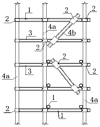
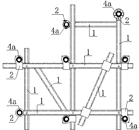
[0037] Example 1: See Figure 8 with Picture 9 , For a certain building structural concrete project, the formwork support under the girder adopts welded horizontal sleeved lattice columns. The cross section of the beam 8 is 500×1400 mm. In the same plane, each welded horizontal sleeve 3 is welded at the intersection with a φ48.3×3.6mm round steel pipe. 2 vertical horizontal rods, 4 horizontal horizontal rods, and welded pipe clamps on the vertical horizontal rods are used as connecting pieces 2. The welded horizontal sleeve 3 is connected to the circular steel pipe vertical rod 4a through the connecting piece 2 to form a welded horizontal sleeve type lattice column. The vertical and horizontal spacing of the uprights 4a is 400×400 mm, and the spacing of the welded horizontal sleeves 3 of the lattice column in the height direction is 600 mm. The lattice column upright 4a supports the main wooden keel under the girder template through the adjustable support 9. Other overall s...

Embodiment 2

[0038] Example 2: See Picture 10 , A double-row scaffolding project on the outer wall of a construction project. The floor plan of a building is 11, the horizontal distance of the scaffolding pole 4a is 1.05m, the vertical distance is 1.5m, the step distance is 1.8m, the distance from the center of the inner pole to the outer wall of the building is 0.3m, and the connecting wall is 2 steps and 2 spans. The scaffold adopts welded horizontal sleeve type lattice column. Each welding horizontal sleeve 3 is formed by welding round steel pipes of φ48.3×3.6mm. The welding horizontal sleeve 3 adopts different plane forms and welding methods at the straight section and the corner respectively. The straight line section is in the form of 1 span plus 2 sides picking out in the longitudinal direction, divided into 2 layers, the vertical horizontal rod is on the top, the horizontal horizontal rod is on the bottom, and the bolts and spacer blocks are welded at the overlapped place. The lo...


PUM


Abstract

The invention relates to the technical field of special members for construction or construction of other buildings, in particular to a welding horizontal sleeve type lattice column. In order to solve the technical problems, the adopted technical scheme is that in a horizontal plane, welding horizontal sleeves (3) are formed by welding a plurality of horizontal poles (1) in a one-layer or multiple-layer manner, are connected to the connecting horizontal poles (1) and vertical uprights (4a), or are further connected to vertical braces (4b), so as to form the welding horizontal sleeve type lattice column. Compared with the prior art, the welding horizontal sleeve type lattice column provided by the invention has the advantages as follows: compared with a round bar steel tube single vertical upright, the lattice column has low probability of instability, solves the difficult problems of safety of a scaffold and a template bracket, and can be matched with a current fastener type scaffold and a bearing and inserting type disc buckling type scaffold; and the welding horizontal sleeve is an instrument type member, so that the quality can be controlled easily. The lattice column can also be used as a construction platform and a structural column.

Description

technical field [0001] The invention relates to a welded horizontal sleeve type lattice column in the technical field of special components for construction of buildings and other structures. Background technique [0002] Formwork brackets and scaffolding have been standardized at present. However, safety accidents still occur frequently. Formwork brackets and scaffolds are connected according to the pole connection methods, such as fastener type, bowl button type, socket type disc button type and so on. But no matter what, it is easy to lose stability with the single vertical pole of the garden steel pipe as the basic component, which is one of the main reasons for the frequent occurrence of safety accidents. There is also portal-type steel pipe scaffolding, the external rigidity of the portal frame is poor, and each layer of vertical poles has connecting rod joints, so the construction quality is difficult to control. [0003] In addition, there is an assembled lattice ...

Claims


Application Information

Patent Timeline
Patent Type & Authority Applications(China)
IPC IPC(8): E04G1/04E04G7/00
Inventor 蒙理明
Owner 蒙理明
Why Eureka
Try Eureka