High speed railway steel rail flaw detection experiment platform and detection method
An experimental platform and detection method technology, applied in the analysis of solids using sonic/ultrasonic/infrasonic waves, etc., can solve the problem of inability to track real-time monitoring, and the detection results of hand-push flaw detectors are easily affected by environmental and personal subjective factors, misjudgment and problems such as missed judgments, to achieve the effect of simplifying the use of equipment, improving integration, and improving automation
- Summary
- Abstract
- Description
- Claims
- Application Information
AI Technical Summary
Problems solved by technology
Method used
Image
Examples
specific Embodiment approach 1
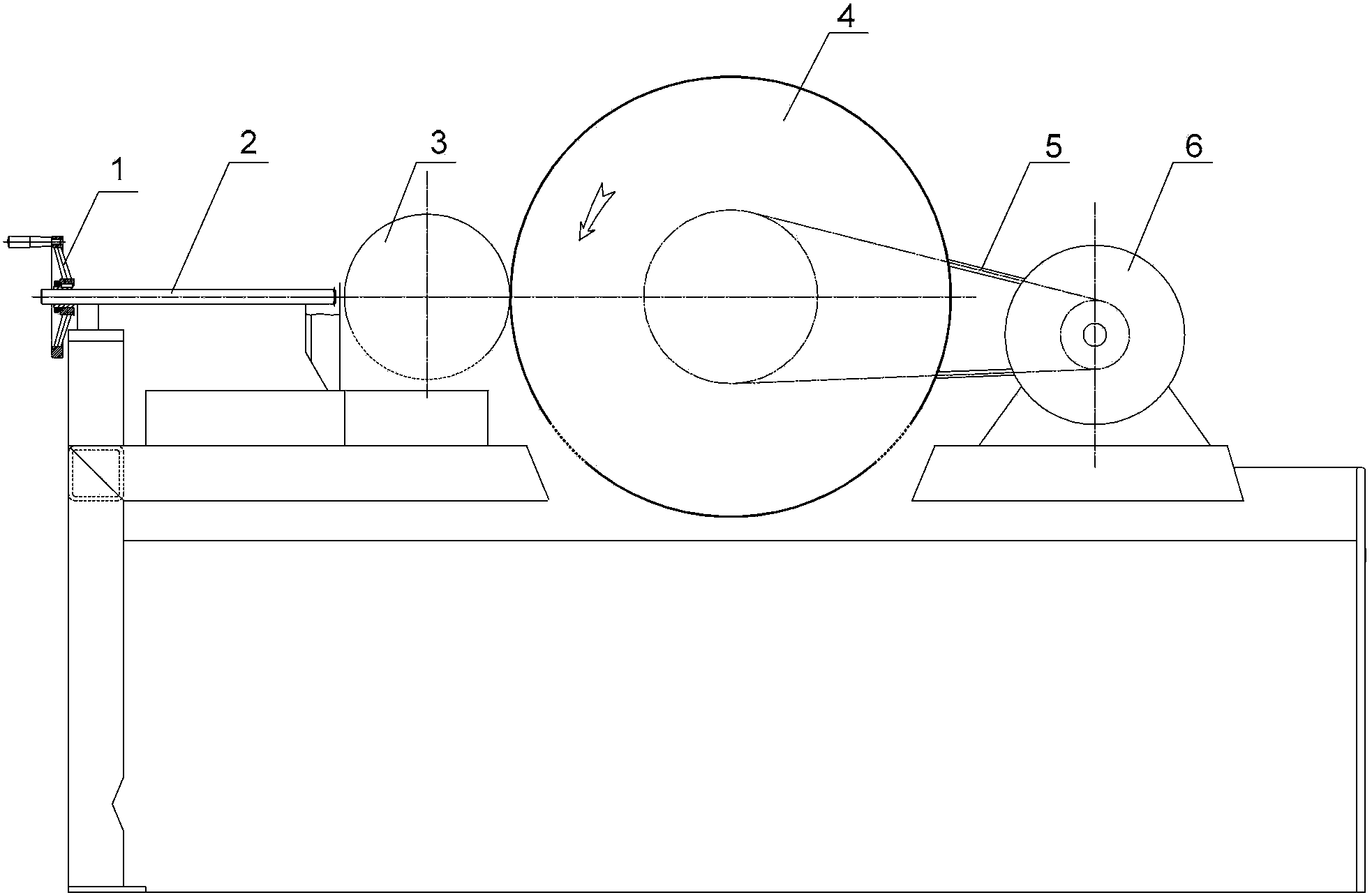
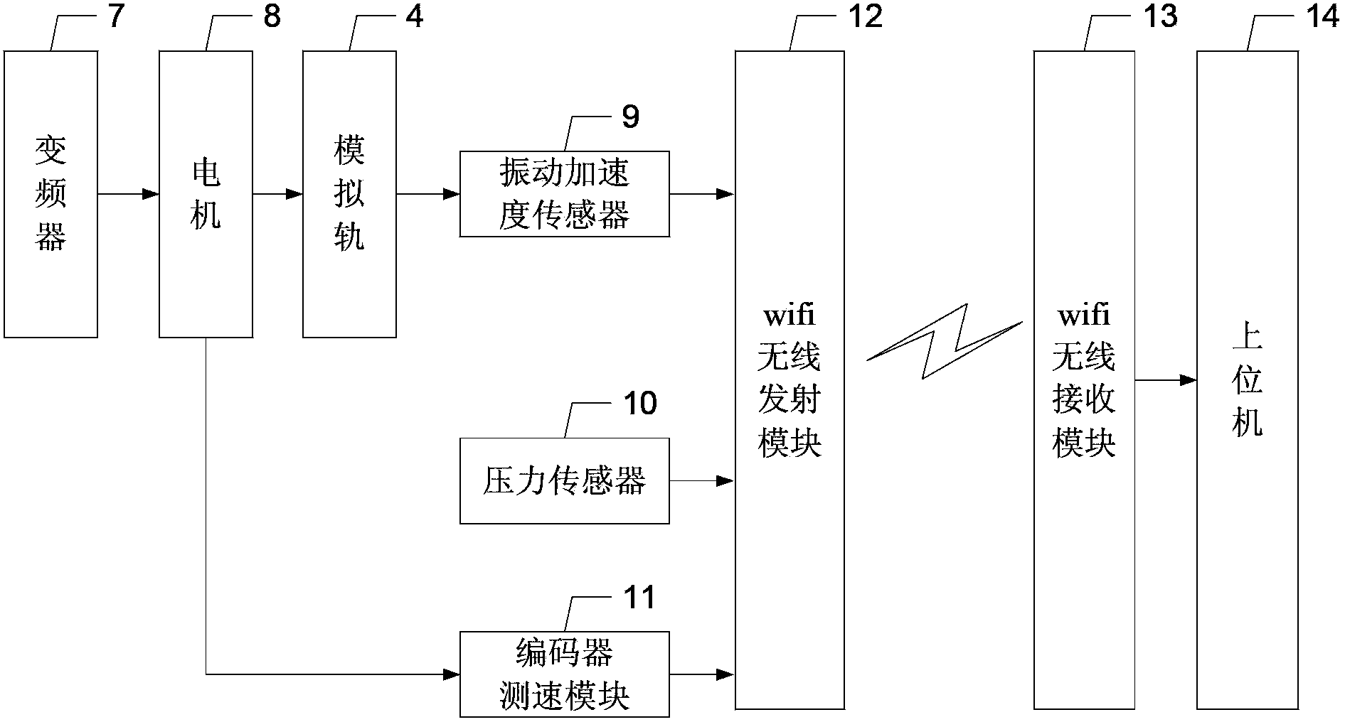
[0032] Specific implementation mode one: the following combination Figure 1 to Figure 7 Describe this embodiment, the high-speed rail rail damage detection experimental platform described in this embodiment includes a pressurizing device 1, a screw mandrel 2, a simulated wheel 3, a simulated high-speed rail 4, a conveyor belt 5, a driving wheel 6, a motor 8, and a vibration acceleration sensor 9, wifi wireless transmitting module 12, wifi wireless receiving module 13 and upper computer 14,
[0033] The simulated high-speed rail 4 is a disc-shaped wheel structure. The transmission connection between the simulated high-speed rail 4 and the driving wheel 6 is realized through the conveyor belt 5. The driving wheel 6 is rotated by the motor 8. The rolling contact between the simulated wheel 3 and the simulated high-speed rail 4 ,
[0034] The pressurizing device 1 pressurizes the simulated wheel 3 through the screw rod 2;
[0035] A vibration acceleration sensor 9 is arranged o...
specific Embodiment approach 2
[0039] Embodiment 2: This embodiment further describes Embodiment 1. It also includes a frequency converter 7 . The output terminal of the frequency converter 7 is connected to the input terminal of the speed control signal of the motor 8 . The frequency converter is used to control the magnitude of the rotational speed of the motor 8 .
[0040] A belt pulley is arranged on the driving wheel 6 and the simulated high-speed rail 4, and the two belt pulleys are connected by the conveyor belt 5. The driving wheel 6 is driven by the motor 8 to rotate, and the driving wheel 6 drives the simulated high-speed rail 4 to rotate by the conveyor belt 5.
[0041] Damage signals at different simulated vehicle speeds can be obtained by controlling the rotational speed of the motor 8 .
[0042] simulated speed Its derivation process is:
[0043] let n 1 is the speed of motor 8, n 2 is the rotational speed of the simulated rail 4, d 1 is the pulley diameter on the drive pulley 6, d 2 is...
specific Embodiment approach 3
[0045] Specific embodiment three: this embodiment will further explain embodiment one, and it also includes pressure sensor 10, and pressure sensor 10 is used for detecting the pressure signal that pressurizing device 1 applies to simulated wheel 3, and the pressure signal output terminal of pressure sensor 10 is connected with The pressure signal input end of the wifi wireless transmitting module 12 is connected.
[0046] The simulated vehicle weight, that is, the pressure value can be measured by the pressure sensor 10 on the device. The pressure sensor 10 adopts the SH-20K digital display pressure gauge of Santo Company. By applying different pressure values, different simulated vehicle weights can be obtained. below the damage signal.
PUM
 Abstract
Description
Claims
Application Information
 - R&D
- Intellectual Property
- Life Sciences
- Materials
- Tech Scout
- Unparalleled Data Quality
- Higher Quality Content
- 60% Fewer Hallucinations
Browse by: Latest US Patents, China's latest patents, Technical Efficacy Thesaurus, Application Domain, Technology Topic, Popular Technical Reports.
© 2025 PatSnap. All rights reserved.Legal|Privacy policy|Modern Slavery Act Transparency Statement|Sitemap|About US| Contact US: help@patsnap.com


