
Tea strip tidying machine capable of reducing temperature

A technology for a tea organizer and rack, which is applied in the direction of tea processing before extraction, can solve the problems of difficult heat dissipation, machine loss, and affecting the working time of the tea organizer.

Active Publication Date: 2013-08-07
镇江市水木年华现代农业科技有限公司
View PDF9 Cites 1 Cited by
  • Summary
  • Abstract
  • Description
  • Claims
  • Application Information

AI Technical Summary

Problems solved by technology

[0003] The strip machine is one of the key equipment for green tea greening and shaping. It has been widely used in the tea processing production line. The tea leaves are thrown, collided, rubbed, squeezed and other forces in the reciprocating spherical tank to make the shape. At the same time, corresponding physical and biochemical changes of tea leaves occur under the heat of the heating device: to inactivate the activity of polyphenol oxidase, evaporate part of the water, volatilize the smell of green grass, soften the tissue, and achieve the purpose of finishing and shaping; in the existing Under the advanced technology, the working environment of the variable frequency motor of the tea slitting machine has the problem of high temperature and difficulty in heat dissipation, which will directly affect the working time of the tea slicing machine, and the high temperature will cause the loss of the machine and shorten the service life of the slicing machine

Method used


Image

  • Tea strip tidying machine capable of reducing temperature
  • Tea strip tidying machine capable of reducing temperature

Examples


Embodiment Construction

[0012] Below in conjunction with the accompanying drawings and specific embodiments, the cooling tea strip organizer of the present invention will be further described in detail.

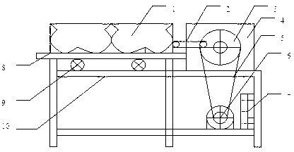
[0013] As shown in the figure, the cooling tea strip organizer of the present invention includes a frame 8 and a U-shaped trough pot 1 arranged above the frame 8. Two U-shaped trough pots 1 are arranged side by side. An electric control box 4 is arranged on one side, and a roller 9 is arranged at the bottom end of the U-shaped trough pot 1, which is convenient for the horizontal vibration of the U-shaped trough pot; the bottom section of the U-shaped trough pot 1 is two connected curved surfaces; There is a heating device 10 located directly below the U-shaped grooved pot 1 to provide a suitable temperature in the U-shaped grooved pot. One side of the U-shaped grooved pot 1 is provided with a driving mechanism for driving the U-shaped grooved pot 1 to vibrate, and the driving mechanism is connected t...


PUM


Abstract

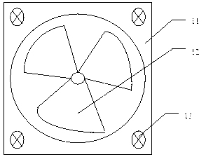
The invention discloses a tea strip tidying machine capable of reducing temperature. The tea strip tidying machine comprises a rack and U-shaped groove pots, wherein idler wheels are arranged at the bottom ends of the U-shaped groove pots, the sections of the bottom surfaces of the U-shaped groove pots are of two connected curved surface structures, a heating device positioned right below the U-shaped groove pots is arranged on the rack, a drive mechanism used for driving the U-shaped groove pots to vibrate is arranged at one sides of the U-shaped groove pots, a motor is connected to the drive mechanism, and a heat radiating device just facing the motor is arranged at the inner side of the rack. After the structure is adopted, space capacities of the groove pots are increased, the curvature radiuses of the lower half part of the U-shaped groove pots are larger, and larger work spaces of the groove pots can be provided, so that the space utilization ratio is increased; by utilizing the principle that hot air ascends, and cold air descends and is accumulated, cold air in the lower layer is sucked by an air inlet so as to cool a frequency variable motor, and the temperature inside the tea strip tidying machine is controlled by using air flowing, and thus the frequency variable motor of the tea strip tidying machine is protected. The tea strip tidying machine is simple in structure; and a protection part is additionally arranged in a core part of the tea strip tidying machine, and thus the service life of the tea strip tidying machine is prolonged.

Description

[0001] technical field [0002] The invention relates to a tea strip sorting machine, in particular to a cooling tea strip sorting machine, which belongs to automatic tea processing equipment. Background technique [0003] The strip machine is one of the key equipments for green tea fixing and shaping. It has been widely used in tea processing production line. At the same time, the corresponding physical and biochemical changes of tea occur under the heat of the heating device: to passivate the activity of polyphenol oxidase, evaporate part of the water, volatilize the smell of grass, soften the tissue, and achieve the purpose of killing green and shaping; in the existing Under the new technology, the working environment of the frequency conversion motor of the tea stripper has the problem of high temperature and difficult heat dissipation, which will directly affect the working time of the tea stripper, and the high temperature will cause the loss of the machine and shorten...

Claims


Application Information

Patent Timeline
IPC IPC(8): A23F3/06
Inventor 汪月霞
Owner 镇江市水木年华现代农业科技有限公司
Learn More