Supporting and limiting mechanism of drawer sliding rail

A limit mechanism and drawer technology, which is applied to drawers, furniture parts, household appliances, etc., can solve the problems of short service life of drawers, damage to the appearance of furniture, mutual friction, etc., and achieve smooth pulling process, long service life and reliable performance Effect

Active Publication Date: 2013-08-07
伍志勇
View PDF7 Cites 14 Cited by
  • Summary
  • Abstract
  • Description
  • Claims
  • Application Information

AI Technical Summary

Problems solved by technology

It is said that the structure is simple, the bearing weight is large, and the shaking is small, so it is suitable for installation on all furniture; And under the weight of the objects loaded in the drawer, the front end of the drawer will sink, and the sinking degree will become more obvious after a long time of use, especially when the drawer is completely closed, the sinking front of the drawer is more manifested in the tilt of the drawer panel, the drawer panel There is a large gap between the top and the drawer cabinet, which destroys the beauty of the furniture. At the same time, there will be mutual friction between the fixed rail and the movable rail, resulting in a short service life of the drawer.

Method used


Image

  • Supporting and limiting mechanism of drawer sliding rail
  • Supporting and limiting mechanism of drawer sliding rail
  • Supporting and limiting mechanism of drawer sliding rail

Examples


Embodiment Construction

[0021] The present invention will be further described below in conjunction with the accompanying drawings and embodiments.

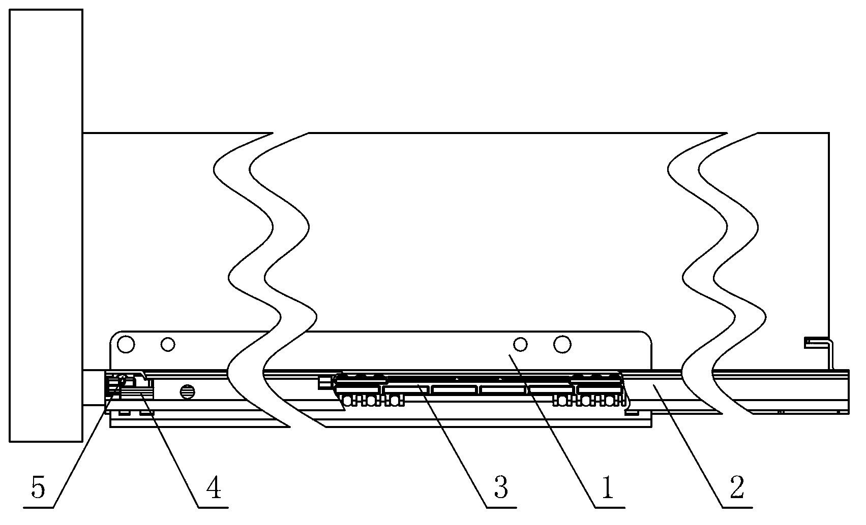
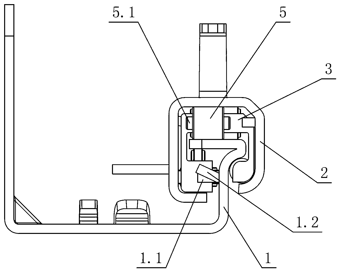
[0022] see Figure 1-8 , the support limit mechanism of the drawer slide rail includes at least a certain slide rail 1 and a moving slide rail 2, and the fixed slide rail 1 and the moving slide rail 2 are slidably connected by a cage 3, wherein the fixed slide rail 1 and the drawer cabinet Connection, the moving slide rail 2 is connected with the drawer bottom plate or the drawer side plate, and the front end of the fixed slide rail 1 is provided with a support limiting mechanism, and the moving slide rail 2 is slidably connected with the fixed slide rail 1 through the support limiting mechanism.

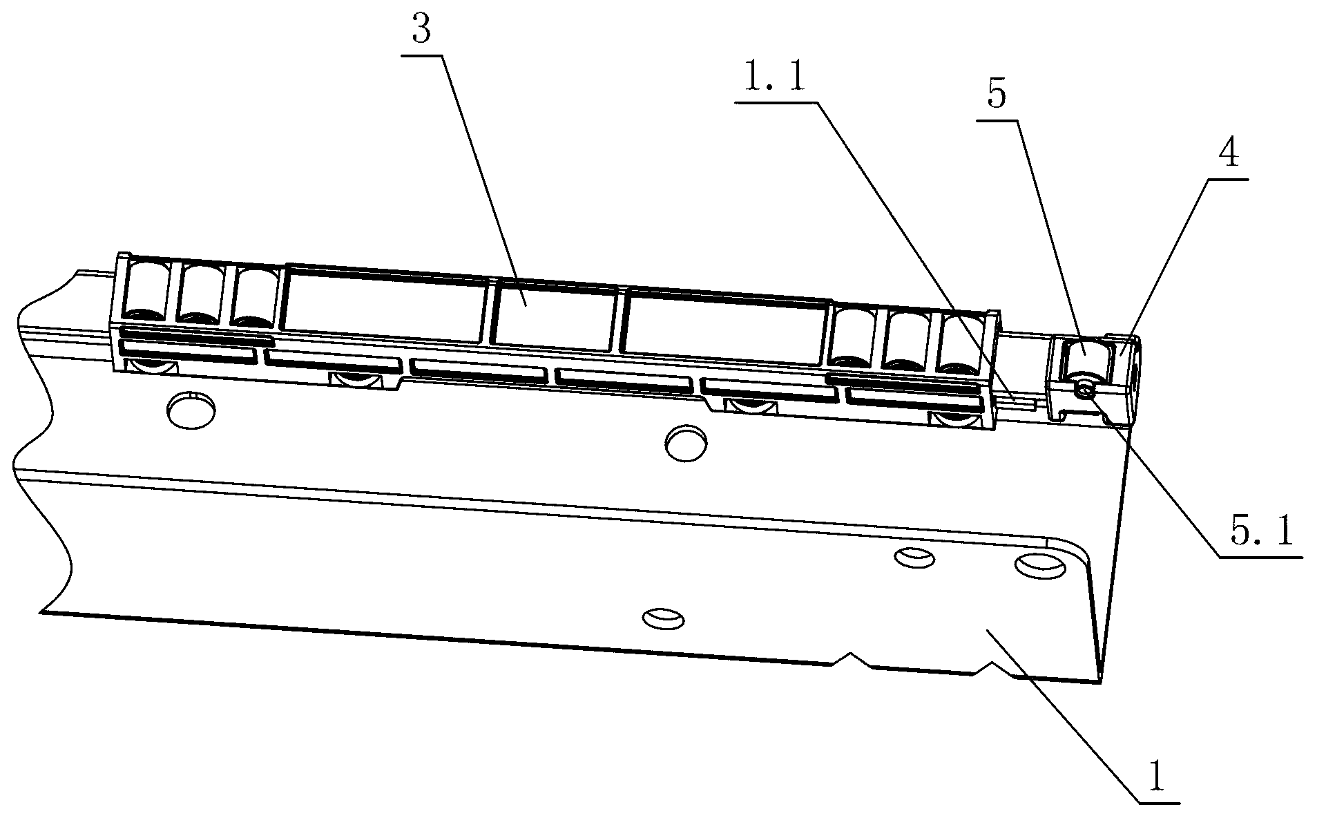
[0023] The cage 3 is a ball type and / or roller type cage; the cage 3 is arranged on the fixed slide rail 1, and is respectively slidably connected with the fixed slide rail 1 and the moving slide rail 2, wherein the fixed slide rail 1 is integrally formed or ...


PUM


Abstract

A supporting and limiting mechanism of a drawer sliding rail comprises at least one fixed sliding rail and at least one movable sliding rail, wherein the fixed sliding rail is in sliding connection with the movable sliding rail through a retainer, the fixed sliding rail is connected with a drawer cabinet body, the movable sliding rail is connected with a drawer base plate or a drawer side plate, the front end of the fixed sliding rail is provided with a supporting and limiting mechanism body, and the movable sliding rail is in sliding connection with the fixed sliding rail through the supporting and limiting mechanism body. The supporting and limiting mechanism body arranged at the front end of the fixed sliding rail comprises at least one rolling wheel seat wrapping the front end of the fixed sliding rail laterally and at least one rolling wheel arranged on the rolling wheel seat and connected with the fixed sliding rail and the movable sliding rail in a rolling mode. When a drawer is drawn out, the fixed sliding rail and the rolling wheel support the movable sliding rail through the retainer, the problem that a gap between the fixed sliding rail and the movable sliding rail is large, the fixed sliding rail and the movable sliding rail cannot be supported mutually, and accordingly sinking and deformation of the front end of the movable sliding rail, collision and friction between the front end and the fixed sliding rail and the like are caused is solved while the weight of the drawer is increased, and accordingly the drawer cannot swing laterally and shake vertically when drawn out and pushed into.

Description

technical field [0001] The invention relates to a drawer slide rail, in particular to a support and position-limiting mechanism of the drawer slide rail. Background technique [0002] Chinese Patent Document No. CN202636185U disclosed a drawer guide rail structure on January 2, 2013, including a fixed rail and a movable rail. There is a cage between them; the upper surface of the horizontal side of the fixed rail bearing part has a concave first raceway; the lower surface of the horizontal side of the movable rail also has a concave second raceway, and the gap between the first raceway and the second raceway is installed. The first ball is embedded; the lower ends of the two vertical sides of the movable rail have first bending parts; the two first bending parts of the movable rail are respectively opposite to the two triangular hypotenuses of the fixed rail, and each first bending part Second balls are installed respectively between the triangular hypotenuse of the fixed r...

Claims


Application Information

Patent Timeline
Patent Type & Authority Applications(China)
IPC IPC(8): A47B88/10A47B88/493
Inventor 伍志勇
Owner 伍志勇
Why Eureka
Try Eureka