Forging mould and molding method of metal casing applied to electronic device

A forming method and technology for metal casings, applied in forging/pressing/hammer devices, manufacturing tools, metal processing equipment, etc., can solve the problems of inability to form casing blanks, long machining time for metal casings, and high production costs

Active Publication Date: 2013-08-07
亚超特工业有限公司
View PDF19 Cites 32 Cited by
  • Summary
  • Abstract
  • Description
  • Claims
  • Application Information

AI Technical Summary

Problems solved by technology

It solves the problems in the prior art that the machining time of the metal shell of the electronic device is long, the shell blank cannot be formed to reduce the amount of subsequent machining, the production cost is high, and the material utilization rate is low.
The present invention can also solve the problem of high forging pressure and difficult forming of the web substructure in the existing forging technology of shell blanks with thin webs

Method used


Image

  • Forging mould and molding method of metal casing applied to electronic device
  • Forging mould and molding method of metal casing applied to electronic device
  • Forging mould and molding method of metal casing applied to electronic device

Examples


Embodiment Construction

[0151] Various embodiments of the present invention will be described in detail below in conjunction with the accompanying drawings. However, these embodiments do not limit the present invention, and any structural, method or functional changes made by those skilled in the art according to these embodiments are included in the protection scope of the present invention.

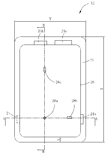
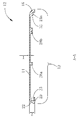
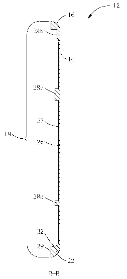
[0152] Figure 1A to Figure 1C and figure 2 Shown is a typical structure of an integrated metal casing 12 applied to a portable electronic device (such as a tablet computer), which is formed from a single piece of metal through integral molding. Figure 1A is a top view of the cavity of the metal shell, Figure 1B for Figure 1A The A-A section diagram of Figure 1C for Figure 1A The B-B cross-sectional view. The metal shell 12 is composed of a web 26 and a frame extending from the periphery of the web 26 . In the present invention, unless otherwise specified, "web" and "metal shell web" both refer to...


PUM

PropertyMeasurementUnit
lengthaaaaaaaaaa
widthaaaaaaaaaa
thicknessaaaaaaaaaa

Abstract

The invention provides a forging mould and a molding method of a metal casing applied to an electronic device. A metal plate can be molded in a forging and pressing mode into a blank of the metal casing with less following machining quantity through the mould, and the blank of the casing is subjected to a small amount of machining to form the metal casing. The mould and the method solve the problem in the prior art that the metal casing of the electronic device is long in machining time, the blank of the casing with less following machining quantity cannot be molded, production cost is high, material utilization rate is low and the like.

Description

technical field [0001] The invention relates to a forging mold and a forming method applied to a metal shell of an electronic device. Background technique [0002] The shape of a 3C electronic device (Computer, Communication and Consumer electronic) is generally a flat rectangular parallelepiped. Its shell is usually a thin drawer-like concave shape, and a shell cavity is surrounded by a central thin web and surrounding frame substructures. The outer front surface of the shell is generally a plane, but it can also be designed as an arc. The outer surface of the surrounding frame is a plane or an arc surface. The web and frame in the concave cavity are usually designed with a web substructure and a frame substructure, as a structure for installing other components (such as studs, bosses, buckles and hinged edges, etc.) or as a strengthening structure for the shell (such as Reinforcing ribs and ribs, etc.). Human-machine communication interfaces such as display screens and...

Claims


Application Information

Patent Timeline
Patent Type & Authority Applications(China)
IPC IPC(8): B21J13/02B23P15/00
Inventor 彭跃南聂存珠陈学军曲峰刘铭曲荣生
Owner 亚超特工业有限公司
Why Eureka
Try Eureka