Double-track electrified railway section post main wiring with capacitive electrical device
A technology for electrified railways and electrical equipment, applied in power lines, vehicle parts, transportation and packaging, etc., can solve the problems of inconvenient operation and maintenance, high proportion of railway bridges and tunnels in mountainous areas, and improve cross-region power supply capacity, reduce power loss, improve The effect of power supply capacity
- Summary
- Abstract
- Description
- Claims
- Application Information
AI Technical Summary
Problems solved by technology
Method used
Image
Examples
Embodiment 1
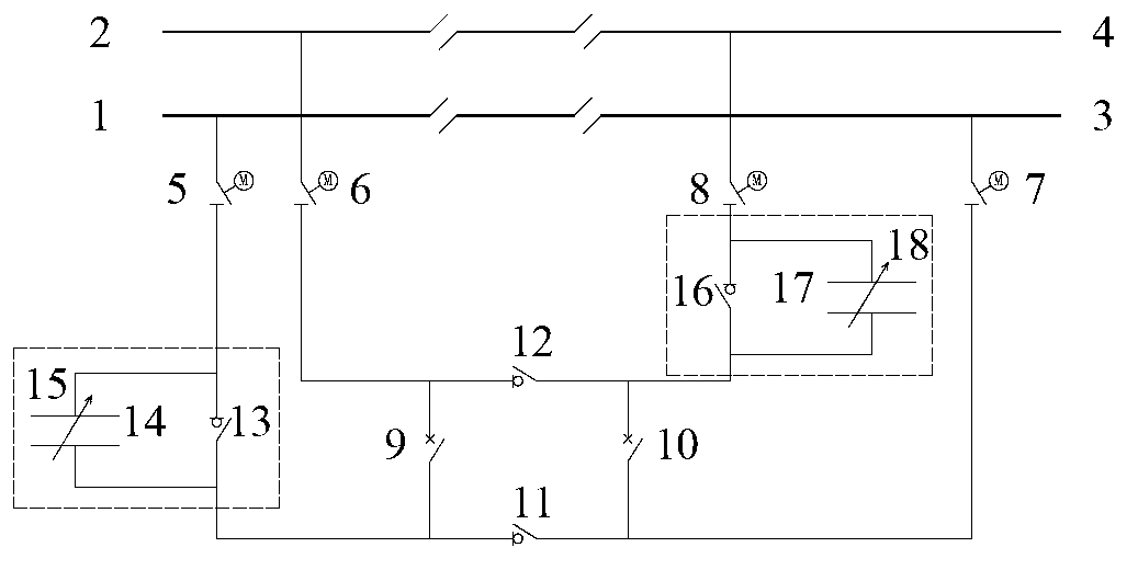
[0026] This embodiment is a partition station with capacitive electrical devices on both sides of the power supply arm, which can be used for parallel power supply on both sides and bidirectional cross-regional power supply. refer to figure 1 The main wiring is connected to two power supply arms, and each power supply arm is provided with an uplink and downlink parallel switch and a set of capacitive electrical equipment. The main wiring includes the first isolating switch 5, the second isolating switch 6, the third isolating switch 7, the fourth isolating switch 8, the first parallel circuit breaker 9, the second parallel circuit breaker 10, the first bypass switch 11, the first 2 Passover switch 12, first capacitive electrical device 15 and its attached first bypass circuit breaker 13, first double-pole isolating switch 14, second capacitive electrical device 18 and its attached second bypass circuit breaker 16 and the second double-pole isolating switch 17.
[0027] refer...
Embodiment 2
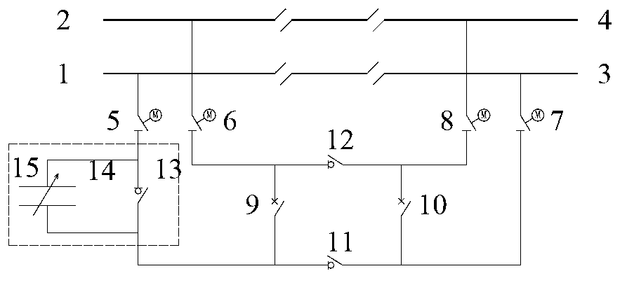
[0039] This embodiment is a partition station with capacitive electrical device on only one power supply arm, double-sided parallel power supply and bidirectional cross-regional power supply. Such as figure 2As shown, the main wiring is connected to two power supply arms, and each power supply arm is equipped with an uplink and downlink parallel switch, and only one end of the power supply arm has a set of capacitive electrical equipment; the main wiring includes a first isolating switch 5 , the second isolating switch 6, the third isolating switch 7, the fourth isolating switch 8, the first parallel circuit breaker 9, the second parallel circuit breaker 10, the first crossover switch 11, the second crossover switch 12, the first capacitor Sexual electrical device 15 and its attached first bypass circuit breaker 13 and first double-pole isolating switch 14. This embodiment is applicable to the situation where only one power supply arm is a long ramp.
[0040] refer to fig...
Embodiment 3
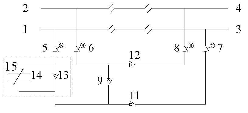
[0052] In this embodiment, only one side of the power supply arm is equipped with a capacitive electrical device, and the power supply can be unilaterally connected in parallel and unidirectionally cross-regional. Such as image 3 As shown, the main wiring is connected to two power supply arms, and only one power supply arm is provided with an uplink and downlink parallel switch and a set of capacitive electrical equipment. The main wiring includes the first isolating switch 5, the second isolating switch 6, the third isolating switch 7, the fourth isolating switch 8, the first parallel circuit breaker 9, the first over-area switch 11, the second over-area switch 12, the first 1 Capacitive electrical device 15 and its attached first bypass circuit breaker 13 and first double-pole isolating switch 14. This implementation mode is applicable to the situation where only one power supply arm is a long ramp and the other power supply arm is very short (referred to as a half-paralle...
PUM
 Abstract
Description
Claims
Application Information
 - R&D
- Intellectual Property
- Life Sciences
- Materials
- Tech Scout
- Unparalleled Data Quality
- Higher Quality Content
- 60% Fewer Hallucinations
Browse by: Latest US Patents, China's latest patents, Technical Efficacy Thesaurus, Application Domain, Technology Topic, Popular Technical Reports.
© 2025 PatSnap. All rights reserved.Legal|Privacy policy|Modern Slavery Act Transparency Statement|Sitemap|About US| Contact US: help@patsnap.com


