Lifting appliance path optimization control system used for container gantry crane

A gantry crane and path optimization technology, applied in safety devices, transportation and packaging, load hanging components, etc., can solve the problems of unpractical identification and positioning and path optimization algorithms, difficult to guarantee reliability, and low intelligence level. Improve work efficiency, reduce crash accidents, and reduce labor intensity

Inactive Publication Date: 2014-12-03
UNIV OF SHANGHAI FOR SCI & TECH
View PDF9 Cites 0 Cited by
  • Summary
  • Abstract
  • Description
  • Claims
  • Application Information

AI Technical Summary

Problems solved by technology

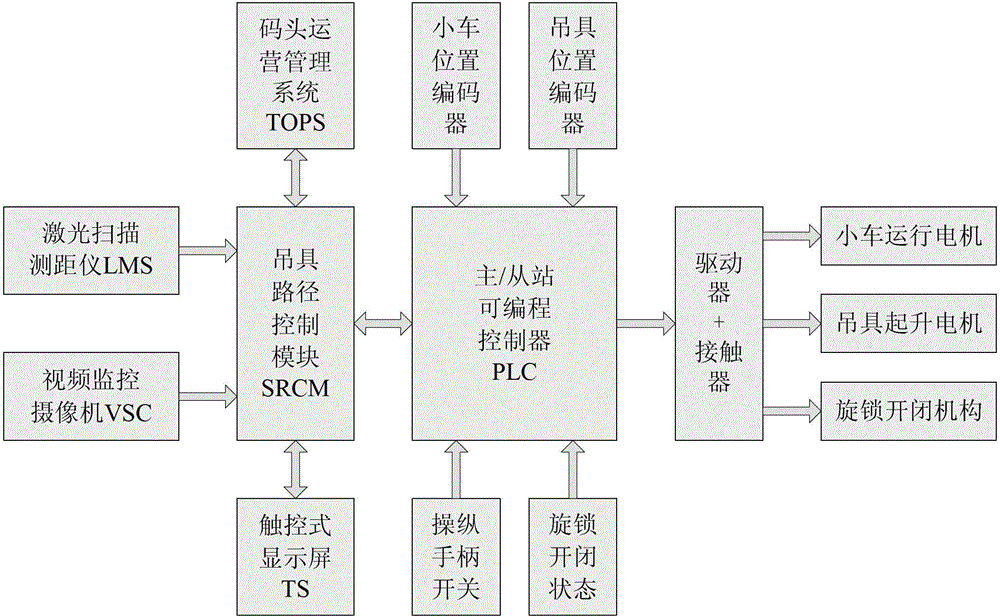
[0004] The technical problem to be solved by the present invention is: in order to overcome many deficiencies such as impractical identification and positioning and path optimization algorithms, long computing time, poor positioning accuracy, low intelligence level, and difficulty in ensuring reliability, which are common in the automatic loading and unloading system of the gantry crane under research, this The invention provides a spreader path optimization control system for container gantry cranes based on laser scanning positioning technology, which can identify and route according to the scanning positioning according to the scheduling instructions of the terminal operation system and the distance measurement information of the vehicle-mounted laser scanning rangefinder. Intelligent algorithm such as optimization control, to carry out positioning identification and path optimization on the outline of the yard and the spreader (or the container to be hoisted), so that the spreader (or the container to be hoisted) can be loaded and unloaded in place along the optimized path

Method used


Image

  • Lifting appliance path optimization control system used for container gantry crane
  • Lifting appliance path optimization control system used for container gantry crane
  • Lifting appliance path optimization control system used for container gantry crane

Examples


Embodiment Construction

[0011] The present invention will be further described below in conjunction with the accompanying drawings.

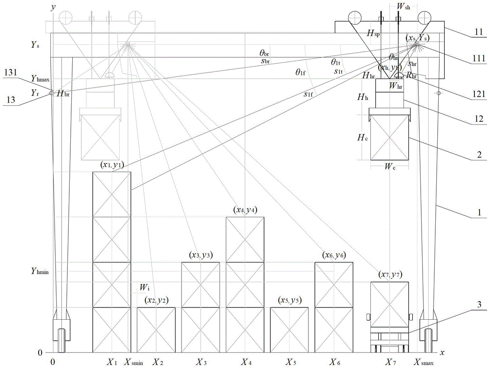
[0012] exist figure 1 In the shown embodiment, the automatic loading and unloading operation of the tire crane in the container yard in the present invention mainly involves: tire crane (1), container (2), truck (3), trolley (11), spreader (12), beam ( 13), laser scanning rangefinder (111), spreader reflection plate (121), beam reflection plate (131) and other components, wherein: the yard containers are stacked vertically under the tire crane in sequence, and the truck passage is located under the tire crane. side, the trolley runs horizontally on the top track of the tire crane, the spreader is connected with the hoisting mechanism on the trolley through the sling, the beam is at the upper position of the leg of the tire crane, the beam reflector is installed vertically on the beam, and the reflector of the spreader is horizontal Installed on the top of the spreader...


PUM


Abstract

The invention relates to a container gantry crane lifting appliance path optimization control system based on a laser scanning positioning technology. The lifting appliance path optimization control system mainly comprises components such as a lifting appliance path control module, a laser scanning range finder, a video surveillance camera and a touch control type display screen, and can carry out positioning identification and path optimization on the contour of a storage yard and a lifting appliance (or a lifted container) according to a scheduling instruction of a wharf operating system and range finding information of a small vehicle-borne laser scanning range finder by using intelligent algorithms such as scanning positioning identification and path optimization control, so that the lifting appliance (or the lifted container) can be loaded and unloaded in place along an optimized path. The lifting appliance path optimization control system can significantly improve the operation efficiency, and reduce the operation energy consumption, container collision accidents and the labor intensity, thus further expanding the scheduling function of the wharf operating system, and being widely used for various tire type and rail type gantry cranes in container yards.

Description

technical field [0001] The invention relates to an automatic loading and unloading control device for a container gantry crane, in particular to a container gantry crane path optimization control system based on laser scanning positioning technology. Background technique [0002] With the continuous development of the world economy, domestic and international trade has been showing a trend of increasing year after year. Due to the significant advantages of large shipping volume and low cost in the shipping industry, the container throughput of the terminal has also risen sharply. The shipment and operation speed of goods are almost completely dependent on Due to the speed of container handling and distribution, the efficiency of container loading and unloading has become a major issue that restricts the cycle of port arrival and departure, improves the level of port logistics services, and reduces the cost of related industrial chains. At present, the container loading and u...

Claims


Application Information

Patent Timeline
Patent Type & Authority Patents(China)
IPC IPC(8): B66C13/16B66C13/22B66C13/04B66C15/00
Inventor 曹民朱爱玺曹至文
Owner UNIV OF SHANGHAI FOR SCI & TECH
Why Eureka
Try Eureka