Motion compensating method applicable to high-speed-mobile-aircraft-mounted SAR (synthetic aperture radar) imaging

A motion compensation, aircraft technology, applied in the field of electronics, can solve problems such as affecting the focusing quality of SAR images, and achieve the effect of reducing the impact and improving the imaging results

Active Publication Date: 2013-08-07
XIDIAN UNIV
View PDF5 Cites 21 Cited by
  • Summary
  • Abstract
  • Description
  • Claims
  • Application Information

AI Technical Summary

Problems solved by technology

In the case of wide swaths, the magnitude of the phase modulation varies with range and seriously affects the focus quality of SAR images
In addition, during the dive phase, the carrier often has a large vertical velocity and vertical acceleration, while the motion error model of conventional airborne SAR generally only considers small lateral velocity and lateral acceleration, and the motion compensation of conventional airborne SAR The method is no longer suitable for SAR carried by high-speed maneuvering aircraft

Method used


Image

  • Motion compensating method applicable to high-speed-mobile-aircraft-mounted SAR (synthetic aperture radar) imaging
  • Motion compensating method applicable to high-speed-mobile-aircraft-mounted SAR (synthetic aperture radar) imaging
  • Motion compensating method applicable to high-speed-mobile-aircraft-mounted SAR (synthetic aperture radar) imaging

Examples


Embodiment Construction

[0024] The technical solutions of the present invention will be described in further detail below with reference to the accompanying drawings and specific embodiments.

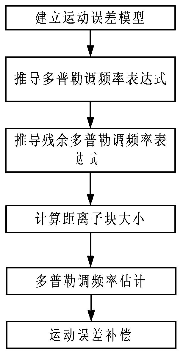
[0025] Build a motion error model

[0026] For coordinates (X 0 ,0,Z 0 ) of P 0 point, the slope range equation for SAR imaging onboard a high-speed maneuvering vehicle is as follows:

[0027] R ( η ) = [ X ( η ) - X 0 ] 2 + [ h 0 + Y ( η ) ] ...


PUM


Abstract

The invention discloses a motion compensating method applicable to high-speed-mobile-aircraft-mounted SAR (synthetic aperture radar) imaging. The motion compensating method includes: establishing a motion error model applicable to high-speed-mobile-aircraft-mounted SAR imaging according to characters of high-speed-mobile-aircraft-mounted SAR imaging; on the basis of the model, analyzing influence on SAR imaging from an inertial navigation error; after distance-direction processing and initial direction Deramp processing are finished, utilizing inertial navigation information and combining with Doppler frequency estimation to obtain residue Doppler frequency modulation information of an echo, utilizing the obtained residue Doppler frequency modulation information to construct a corresponding compensating function to reasonably compensate an error phase, and thereby focusing quality of high-speed-mobile-aircraft-mounted SAR images is effectively improved.

Description

technical field [0001] The invention belongs to the field of electronic technology, and relates to a motion compensation method suitable for high-speed maneuvering aircraft-borne SAR imaging. Background technique [0002] Compared with optical systems, synthetic aperture radar (SAR) has the advantages of all-weather, all-weather and long range. For high-speed maneuvering aircraft, such as missiles, aerospace planes, etc., high-resolution microwave images containing characteristic landforms can be obtained through SAR imaging, and matched with the reference images stored in the database, so that the position coordinates of the aircraft can be calculated from the geometric relationship. , to achieve the purpose of correcting the cumulative error of inertial navigation and improving the guidance accuracy. Therefore, the research on SAR imaging method on high-speed maneuvering aircraft has important practical significance. [0003] For SAR imaging carried by high-speed maneuve...

Claims


Application Information

Patent Timeline
Patent Type & Authority Applications(China)
IPC IPC(8): G01S13/90
Inventor 包敏文珺李亚超周松史林
Owner XIDIAN UNIV
Why Eureka
Try Eureka