Computing method of traction position correction of traction control system

A traction control system and correction calculation technology, applied in the field of traction systems, can solve the problems of untimely adjustment of the working state of the inverter, potential safety hazards, and the influence of safe and accurate transportation of items, and achieve low cost, few fault links, and high reliability. Effect

Inactive Publication Date: 2015-05-13
OCEANOGRAPHIC INSTR RES INST SHANDONG ACAD OF SCI
View PDF6 Cites 0 Cited by
  • Summary
  • Abstract
  • Description
  • Claims
  • Application Information

AI Technical Summary

Problems solved by technology

Due to inaccurate position detection, it will lead to untimely adjustment of the working state of the inverter, which will have a certain impact on the safe and accurate delivery of items, and there are certain safety hazards

Method used


Image

  • Computing method of traction position correction of traction control system
  • Computing method of traction position correction of traction control system
  • Computing method of traction position correction of traction control system

Examples


example 1

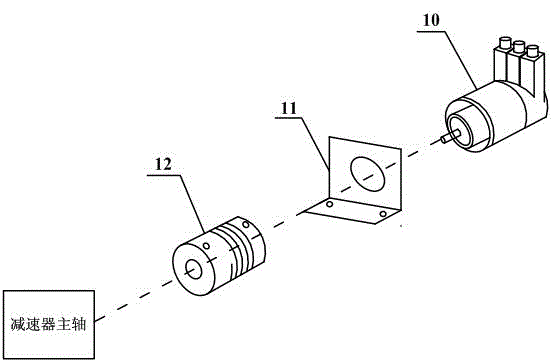
[0071] Example 1, assuming that the maximum detection distance of the multi-turn absolute rotary encoder 10 is L=8000 meters, the length of track 1 is M=350 meters, and the initial sampling position of the multi-turn absolute rotary encoder 10 at the starting point of track 1 Meter. Assuming that the orbital reciprocating vehicle 2 drives from the starting point of the track 1 to the end point, the rotary encoder 10 reverses, and the count value n gradually decreases, then:

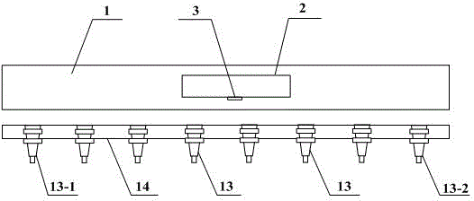
[0072] ①When the orbital reciprocating vehicle 2 passes the i-th magnetic limit switch, the count value output by the rotary encoder 10 The sampling position corresponding to the zero value of the relative encoder count m, the orbital reciprocating vehicle 2 continues to move forward after passing the i-th magnetic limit switch, and the current output real-time count value n is relative to the sampling position corresponding to the zero value of the encoder count m, then first use the formula (2) to...

example 2

[0082] Example 2, assuming that the maximum detection distance of the multi-turn absolute value rotary encoder 10 is L=8000 meters, the length of track 1 is M=350 meters, and the initial sampling position of the multi-turn absolute value rotary encoder 10 at the starting point of track 1 Meter. Assuming that the orbital reciprocating vehicle 2 drives from the starting point of the track 1 to the end point, the rotary encoder 10 rotates forward, and the count value n gradually increases, then:

[0083] ①When the orbital reciprocating vehicle 2 passes the i-th magnetic limit switch, the count value output by the rotary encoder 10 The sampling position corresponding to the count zero value of the relative encoder m, the orbital reciprocating vehicle 2 continues to move forward after passing the i-th magnetic limit switch, and the current output real-time count value n is relative to the sampling position corresponding to the zero value of the encoder count m, then first use...


PUM


Abstract

The invention discloses a traction control system and a traction position correction computing method. The traction control system comprises a steel wire reel transmission system, a rail reciprocation vehicle and a multi-circle absolute value rotary encoder used for detecting rotating position of a steel wire reel, a permanent magnet is mounted on the rail reciprocation vehicle, a magnetic limiting switch is mounted at the starting position of a rail on which the rail reciprocation vehicle travels, the permanent magnet on the rail reciprocation vehicle is just induced by the magnetic limiting switch when the rail reciprocation vehicle reaches to the starting position of the rail, and a controller computes the current traction position of the rail reciprocation vehicle according to the multi-circle absolute value rotary encoder and detection signals fed back by the magnetic limiting switch. The traction control system and the traction position correction computing method can solve the problem about computation error caused by zero point crossing of the rotary encoder, and the traction control system is simple in structure design, low in cost, few in fault links, high in reliability, and capable of providing a powerful technical guarantee to accurate position and transportation of articles.

Description

technical field [0001] The invention belongs to the technical field of traction systems, and in particular relates to an automatic control system that uses a wire rope runner drive system to pull a rail reciprocating vehicle to travel, and a traction position correction calculation method for a rail reciprocating vehicle designed based on the control system. Background technique [0002] In recent years, in some special applications, it is necessary to quickly drag large-tonnage items, and it is necessary to perform automatic control according to the position of the items during dragging, and finally automatically transport the items to the planned location. For the transportation of large-tonnage items, the traction and dragging of the reciprocating vehicle on the track by the wire rope runner transmission system is generally used at present, and the traction control system is used to detect the walking position of the reciprocating vehicle in real time, and then according t...

Claims


Application Information

Patent Timeline
Patent Type & Authority Patents(China)
IPC IPC(8): G05D1/02
Inventor 吕成兴赵娜刘军礼高乾刘波牟华李金萍赵阳李磊周忠海周晓晨蒋慧略惠超张照文
Owner OCEANOGRAPHIC INSTR RES INST SHANDONG ACAD OF SCI
Why Eureka
Try Eureka