Logic timing control circuit and parallel charging and serial discharging control circuit

A timing control circuit and control circuit technology, applied in circuit devices, battery circuit devices, current collectors, etc., can solve the problems of complicated operation, battery short circuit, system burnout, etc., and achieve the effects of convenient use, extended service life and simple structure

Inactive Publication Date: 2013-08-07
艾何示
View PDF8 Cites 20 Cited by
  • Summary
  • Abstract
  • Description
  • Claims
  • Application Information

AI Technical Summary

Problems solved by technology

Therefore, it is necessary to manually toggle the switch to achieve this operation. Not only is the operation complicated, but if the switching sequence of a certain switch in the switch group is wrong, it will cause a short circuit of the battery and burn the entire system instantly.
A switch group without a logic sequence control circuit is like a crossroad without traffic lights, where catastrophic accidents may occur at any time, and has no practical value

Method used


Image

  • Logic timing control circuit and parallel charging and serial discharging control circuit
  • Logic timing control circuit and parallel charging and serial discharging control circuit
  • Logic timing control circuit and parallel charging and serial discharging control circuit

Examples


Embodiment Construction

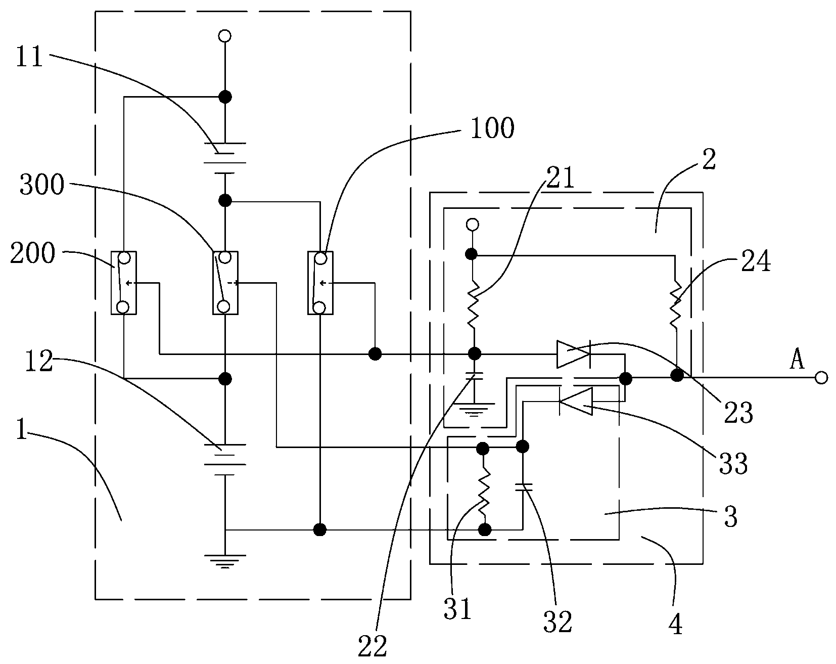
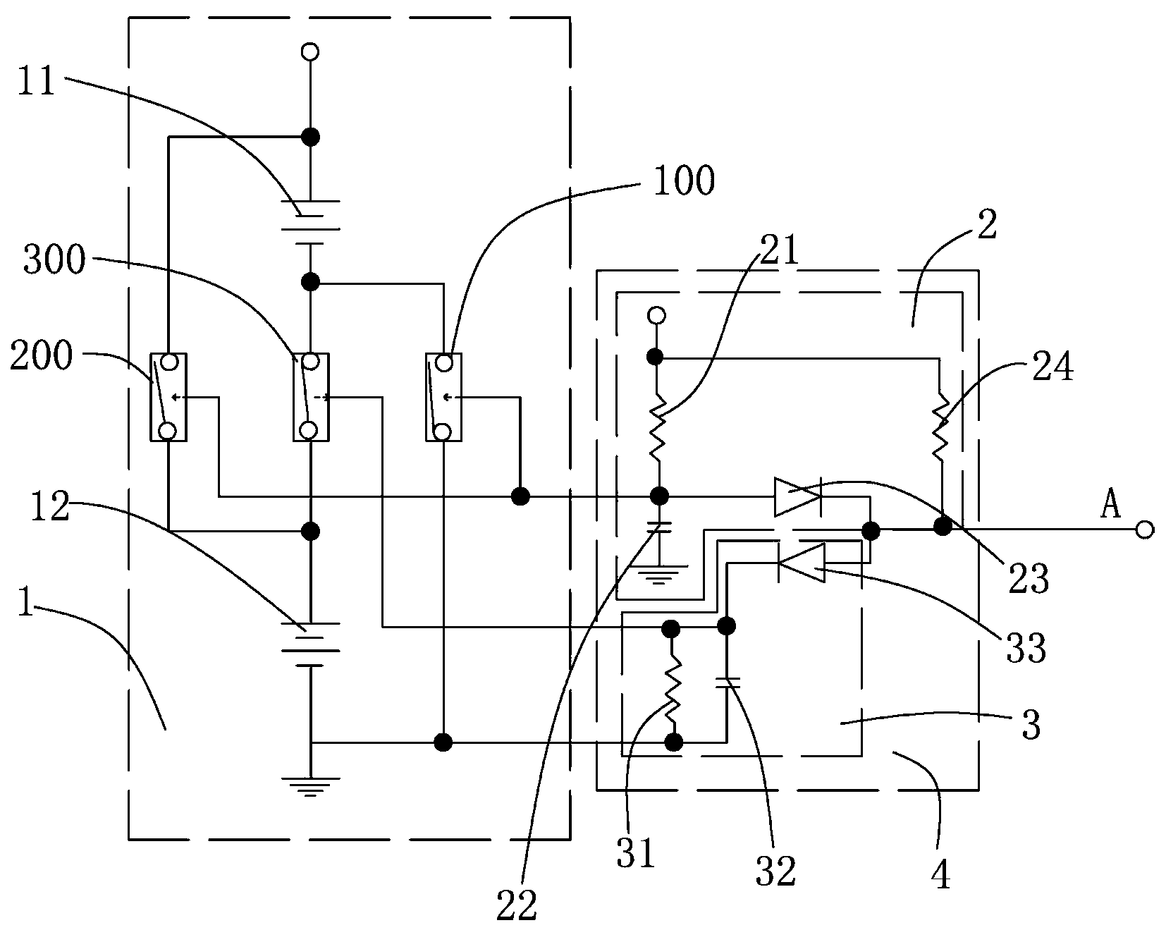
[0027] See figure 1 and figure 2 , figure 1 and figure 2 What is disclosed is a logic sequence control circuit and a control circuit for parallel charging and series discharge, including a first group of switch control circuits 1 and a logic sequence control circuit 4, and the first group of switch control circuits 1 includes first batteries connected in parallel group 11 and a second battery group 12, the output terminal of the first battery group 11 is connected in series with the first switch 100, the input terminal of the second battery group 12 is connected in series with the second switch 200, and the third switch 300 is set at the Between the input end of the first switch 100 and the output end of the second switch 200 , the working states of the first switch 100 and the second switch 200 are opposite to the working states of the third switch 300 .

[0028]The logic timing control circuit 4 includes a first logic timing control circuit 2 and a second logic timing c...


PUM


Abstract

The invention discloses a logic timing control circuit. The logic timing control circuit comprises a first logic timing control circuit and a second logic timing control circuit, wherein the first logic timing control circuit comprises a first unidirectional connection element which contains at least a PN junction and a first time delay circuit which is electrically connected with the positive pole of the first unidirectional connection element which at least contains the PN junction; the second logic timing control circuit comprises a second unidirectional connection element which at least contains the PN junction and a second time delay circuit which is electrically connected with the negative pole of the second unidirectional connection element which contains at least the PN junction; and the common connection point of the negative pole of the first unidirectional connection element which contains at least the PN junction and the positive pole of the second unidirectional connection element which contains at least the PN junction is provided with a control signal input end. The logic timing control circuit is adopted so as to mutually switch the parallel charging with the serial discharging of a plurality of battery packs; and the logic timing control circuit has the advantages that the logic timing control circuit is simple in structure and convenient to use, the battery packs cannot be caused to shortcircuit in a mutual switching process, and the service lives of the battery packs are prolonged.

Description

technical field [0001] The invention relates to a logic sequence control circuit with simple structure, batteries connected in parallel during charging, and batteries connected in series during discharge, and a control circuit for parallel charging and serial discharging. Background technique [0002] With the development of science and technology, various digital products such as smartphones, MP3, MP4, PDA, handheld computers, and handheld game consoles have become necessary supplies for people's lives. However, when these battery-powered devices are limited by battery capacity, A battery that is too low to function normally must be recharged immediately to resume normal operation. The mobile power supply is a portable charger that integrates power supply and charging functions. The mobile power supply can provide power (power supply or charge) for a variety of digital products anytime and anywhere in the mobile state, which brings many conveniences to people's lives. It h...

Claims


Application Information

Patent Timeline
Patent Type & Authority Applications(China)
IPC IPC(8): H03K17/28H02J7/00
Inventor 艾何示
Owner 艾何示
Why Eureka
Try Eureka