Eureka AIR delivers breakthrough ideas for toughest innovation challenges, trusted by R&D personnel around the world.

Double-side cooling concentric tube-in-tube type sulfonating reactor

A technology of sulfonation reactors and concentric sleeves, applied in chemical instruments and methods, chemical/physical processes, etc., can solve problems such as temperature out of control, long production cycle, increased by-products, etc., to achieve easy temperature control and pressure bearing capacity Strong, large heat transfer area

Active Publication Date: 2014-12-24
SHENYANG INSTITUTE OF CHEMICAL TECHNOLOGY
View PDF6 Cites 12 Cited by
  • Summary
  • Abstract
  • Description
  • Claims
  • Application Information

AI Technical Summary

Problems solved by technology

This reaction method has many defects that cannot be overcome by itself: firstly, the heat transfer area of ​​the reactor is small, and the reaction heat removal rate is slow, which leads to slow addition of sulfonating agent and long production cycle; secondly, continuous dropwise addition of sulfonating agent to the reactor Inside, sulfur trioxide is in continuous contact with the reaction product, resulting in a deepened reaction of the early reaction product and an increase in by-products; in addition, there is a huge potential safety hazard in this reaction process. If the heat cannot be removed in time, the temperature will be out of control and a safety accident will occur.
However, after a large number of experiments, it was found that this reaction process is often difficult to control, because the two materials involved in the reaction are close to the theoretical feed ratio, and the reaction in the initial reaction section of the reaction device is very violent, and the reactor with a common cooling jacket cannot be removed quickly. Reaction heat, leading to temperature out of control, the reaction can not continue

Method used


Image

  • Double-side cooling concentric tube-in-tube type sulfonating reactor
  • Double-side cooling concentric tube-in-tube type sulfonating reactor
  • Double-side cooling concentric tube-in-tube type sulfonating reactor

Examples


Embodiment

[0035] This embodiment is an application example of the present invention in the sulfonation of m-nitrobenzene with sulfur trioxide in liquid phase.

[0036] Three double-sided cooling concentric sleeve-type sulfonation reactors, the diameter of the reaction sleeve is DN25, and the effective reaction length is 1.2m; they are connected in series to form the initial sulfonation reactor, and then eight SK-type static mixers of DN20 are connected in series. A single pipe is 1.2m long; it serves as a sustaining reactor. During the experiment, the reaction temperature was controlled at 90°C±5°C, the flow rate of m-nitrobenzene was 200L / h, and the flow rate of sulfur trioxide was 100L / h. The experimental results showed that the content of liquid m-nitrobenzenesulfonic acid was 96.5%, and the mass of nitrosulfone Content 2.5%.

[0037] The experimental results show that the reactor can quickly remove the heat of reaction, the reaction temperature can be controlled sensitively, the pr...


PUM


Abstract

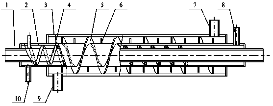
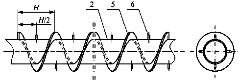
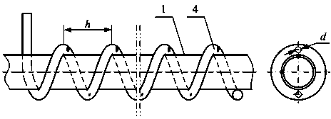
The invention relates to a double-side cooling concentric tube-in-tube type sulfonating reactor. The double-side cooling concentric sleeve type sulfonating reactor comprises a cooling inner tube (1), a reaction sleeve (2), a cooling sleeve (3), a spiral jet pipe, a spiral flow deflector, spoiler columns (6), a cooling sleeve outlet pipe (7), a reaction sleeve outlet pipe (8), a cooling sleeve inlet pipe (9), a reaction sleeve inlet pipe (10), and the like, wherein the cooling inner tube, the reaction sleeve and the cooling sleeve are arranged in a concentric way, so that a reaction cavity and two heat exchange cavities are formed; furthermore, the spiral jet pipe and the spiral flow deflector are respectively arranged in the reaction cavities, so that the reaction material and a coolant can flow in a spiral way, and mass transfer and heat transfer are synchronously enhanced. The double-side cooling concentric tube-in-tube type sulfonating reactor is rapid in heat exchange speed and safe and reliable in reaction, thus being especially suitable for a continuous sulfonation reaction technology taking liquid-phase sulfur trioxide as a sulfonating agent.

Description

technical field [0001] The invention relates to a casing type reactor, in particular to a double-side cooling concentric casing type sulfonation reactor. Background technique [0002] The sulfonation reaction using liquid-phase sulfur trioxide as the sulfonating agent is usually carried out by dripping in a kettle, that is, the sulfonated substance (such as nitrobenzene) is put into the reaction kettle first, and then the sulfur trioxide is inserted into the bottom. The tube is slowly dropped into the reaction kettle, and the materials are mixed evenly by stirring, and the materials react violently at the same time, releasing a large amount of heat of reaction. The heat of reaction is removed by a coolant in the reactor jacket to maintain the proper reaction temperature. This reaction method has many defects that cannot be overcome by itself: firstly, the heat transfer area of ​​the reactor is small, and the reaction heat removal rate is slow, which leads to slow addition o...

Claims


Application Information

Patent Timeline
Patent Type & Authority Applications(China)
IPC IPC(8): B01J8/06
Inventor 王宗勇孟辉波吴剑华张春梅田瑞朱军
Owner SHENYANG INSTITUTE OF CHEMICAL TECHNOLOGY
Why Eureka
Eureka Blog
Learn More