Eureka AIR delivers breakthrough ideas for toughest innovation challenges, trusted by R&D personnel around the world.

Dimpled enhanced heat exchange tube

A technology of heat exchange tubes and small cells, applied in the direction of tubular elements, heat transfer modification, heat exchange equipment, etc., can solve the problems of inability to enhance heat transfer, unsatisfactory effect of heat transfer enhancement, and inability to generate longitudinal vortices in fluid, etc. Achieve the effect of improving comprehensive heat transfer performance, small fluid resistance, and easy realization

Inactive Publication Date: 2009-10-28
XI AN JIAOTONG UNIV
View PDF4 Cites 22 Cited by
  • Summary
  • Abstract
  • Description
  • Claims
  • Application Information

AI Technical Summary

Problems solved by technology

It is worth noting that the above patents and studies are all spherical cells no matter whether they are convex inward or outward. The concave structure reduces the local flow area and increases the resistance greatly, but it is not good for heat transfer. The enhancement effect is not very ideal; although the outwardly convex structure can increase the flow area without greatly increasing the resistance, it is easy to form a vortex dead zone in the outwardly convex small cells, which cannot effectively control the heat transfer. strengthen
There are only a few foreign literatures mentioning ellipsoidal cytes, but due to the arrangement of cytes, the fluid cannot generate longitudinal vortices.

Method used


Image

  • Dimpled enhanced heat exchange tube
  • Dimpled enhanced heat exchange tube
  • Dimpled enhanced heat exchange tube

Examples


Embodiment 1

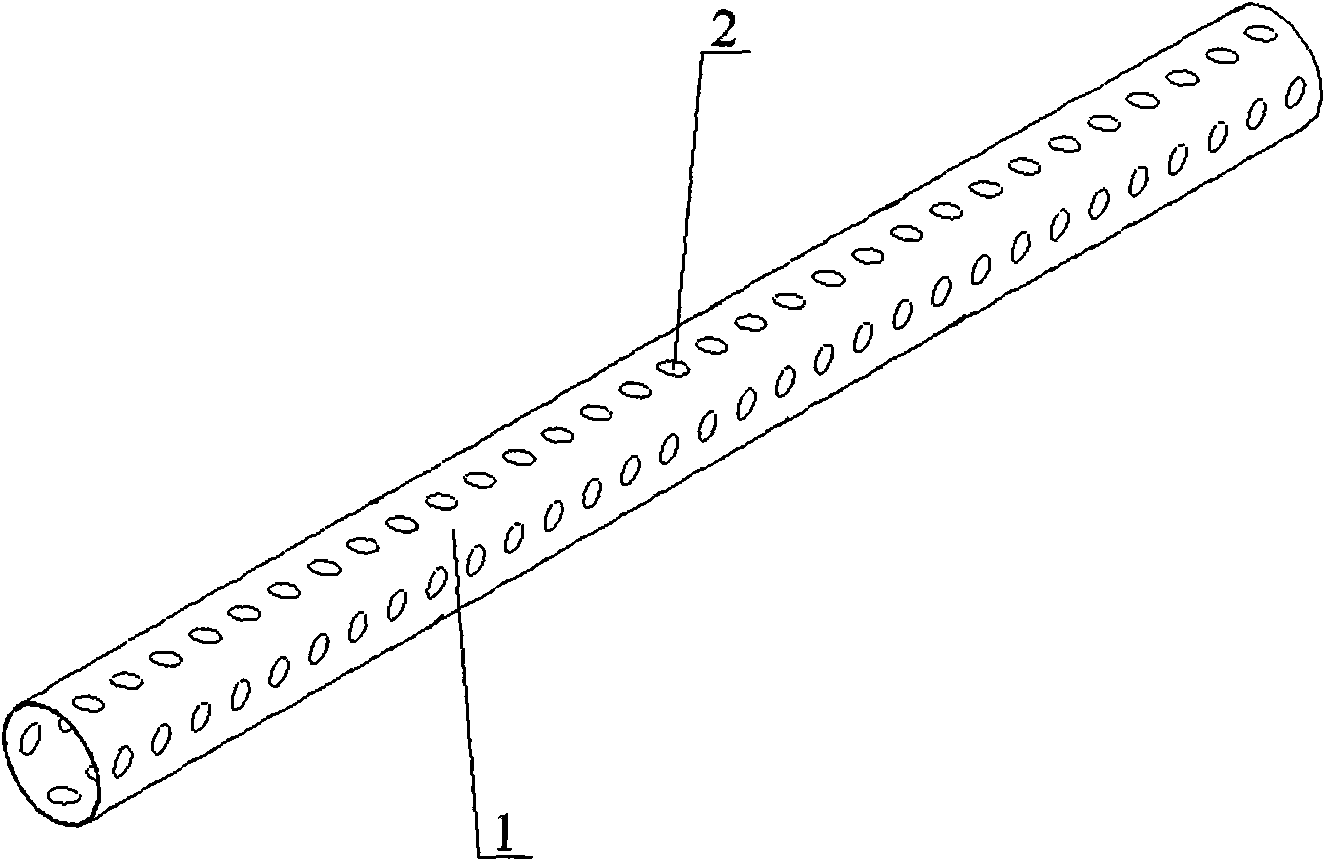
[0013] Example 1, see figure 1 , the present invention includes a base pipe 1 and a group of cytes composed of ellipsoidal crown-shaped cytes 2 protruding from the outer wall of the base pipe 1 to the inside of the base pipe 1 in a certain arrangement and circumferentially distributed on the wall of the base pipe 1, several Tetracyst groups are evenly distributed along the flow direction of the fluid in the base pipe 1 . The long axis of the ellipsoid crown-shaped cyte 1 forms an included angle of 45° with the flow direction of the fluid in the base pipe 1, and the directions of the long axes on the same circular section intersect each other; the projected length of the long axis of the ellipsoid-shaped cyte 1 is 8mm, and the projected length of the minor axis is 4mm; the angular interval θ between the ellipsoidal coronal cytes distributed in the circumferential direction of the base tube is 60°. The number of ellipsoidal corona-shaped tetracytes on the same circumferential s...


PUM


Abstract

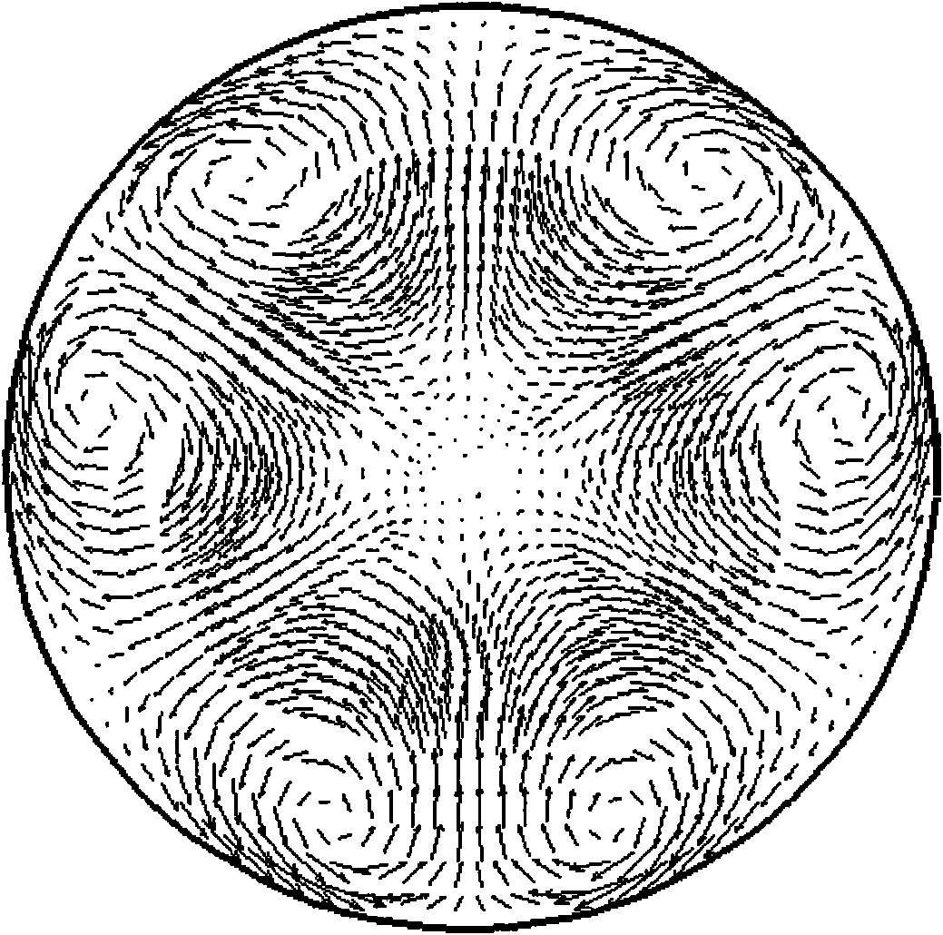
The invention relates to a dimpled enhanced heat exchange tube, which comprises a base tube and dimple groups formed by ellipsoid crown type dimples which are processed from the external wall of the base tube to the inside according to certain array on the tube wall of the base tube, wherein the dimple groups are evenly distributed along the axial direction of the base tube according to certain cycle and separation distance. Because the base tube is processed with the novel dimples, the comprehensive performance of the heat exchange tube is improved compared with the former similar heat exchange tubes. The dimpled enhanced heat exchange tube has the following characteristics: 1, the ellipsoid crown type dimples increase the heat transfer area in the tube and increase the flow velocity of fluid; 2, boundary layers of the inner wall of the tube are destroyed more effectively; 3, the ellipsoid crown type dimples having certain included angle with the axial direction make the fluid generate longitudinal vortexes; and 4, the continuous changes of the cross section of the tube and the generated pressure changes increase the turbulivity of the fluid in the tube to further improve the tube side heat exchange coefficient, and while the tube side heat exchange coefficient is improved, the ellipsoid crown type dimples having certain included angle with the axial direction make the fluid generate secondary flow which has smaller increase to the fluid resistance, thus the effect of improving the comprehensive heat exchange performance is achieved.

Description

technical field [0001] The invention relates to a heat exchanger widely used in heat exchange systems in the fields of energy, power, chemical industry, metallurgy, machinery, transportation, aerospace and the like, and in particular relates to a cingular enhanced heat exchange tube. Background technique [0002] Since the tube is the basic component of the shell-and-tube heat exchanger, the research on improving the heat transfer efficiency of the shell-and-tube heat exchanger and reducing its flow resistance is attributed to the heat transfer with or without phase change of the fluid inside and outside the tube. Strengthen research. The structural shape and surface properties of the tube directly affect heat transfer and flow resistance. With the traditional smooth heat exchange tube, as the fluid flows in the tube, the boundary layer formed by the fluid on the wall surface will gradually thicken, which will make the coordination of velocity and temperature gradient worse...

Claims


Application Information

Patent Timeline
Patent Type & Authority Applications(China)
IPC IPC(8): F28F1/40F28F13/02F28F13/12
Inventor 何雅玲王煜雷勇刚
Owner XI AN JIAOTONG UNIV
Why Eureka
Eureka Blog
Learn More