Double-horizontal-shaft continuous stirrer with oppositely arranged inner and outer stirring units

The technology of a stirring device and twin horizontal shafts is applied in the field of stabilized soil material mixers, which can solve the problems of reducing the rigidity of the mixing shaft, worsening the throwing effect, and unfavorable uniform stirring of the stabilized soil material, so as to improve the mixing uniformity and prolong the mixing time. , Improve the effect of the shaft holding phenomenon

Inactive Publication Date: 2015-05-06
CHANGAN UNIV
View PDF7 Cites 9 Cited by
  • Summary
  • Abstract
  • Description
  • Claims
  • Application Information

AI Technical Summary

Problems solved by technology

For example: increasing the length of the mixer will not only reduce the rigidity of the mixer shaft, but also cause large deformation during work, which will affect the service life of the mixer device and external support bearings, and will also increase the overall size of the mixer; reduce the speed of the mixer shaft, although It can reduce the axial movement speed of the material, but at the same time it will also reduce the circumferential stirring speed of the material, which not only causes the material throwing effect in the vertical direction to deteriorate, but also reduces the interaction between the two stirring shafts. The uniform mixing of soil materials is still very unfavorable; multi-stage mixing is to prolong the mixing time through two separate mixers, which also increases additional equipment, resulting in an increase in production costs and floor space

Method used


Image

  • Double-horizontal-shaft continuous stirrer with oppositely arranged inner and outer stirring units
  • Double-horizontal-shaft continuous stirrer with oppositely arranged inner and outer stirring units
  • Double-horizontal-shaft continuous stirrer with oppositely arranged inner and outer stirring units

Examples


Embodiment Construction

[0023] The present invention will be described in further detail below in conjunction with the accompanying drawings.

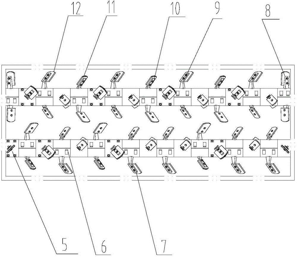
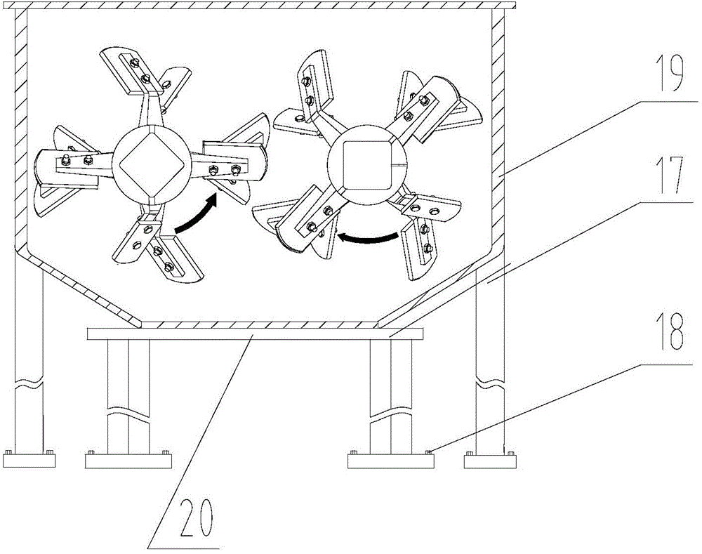
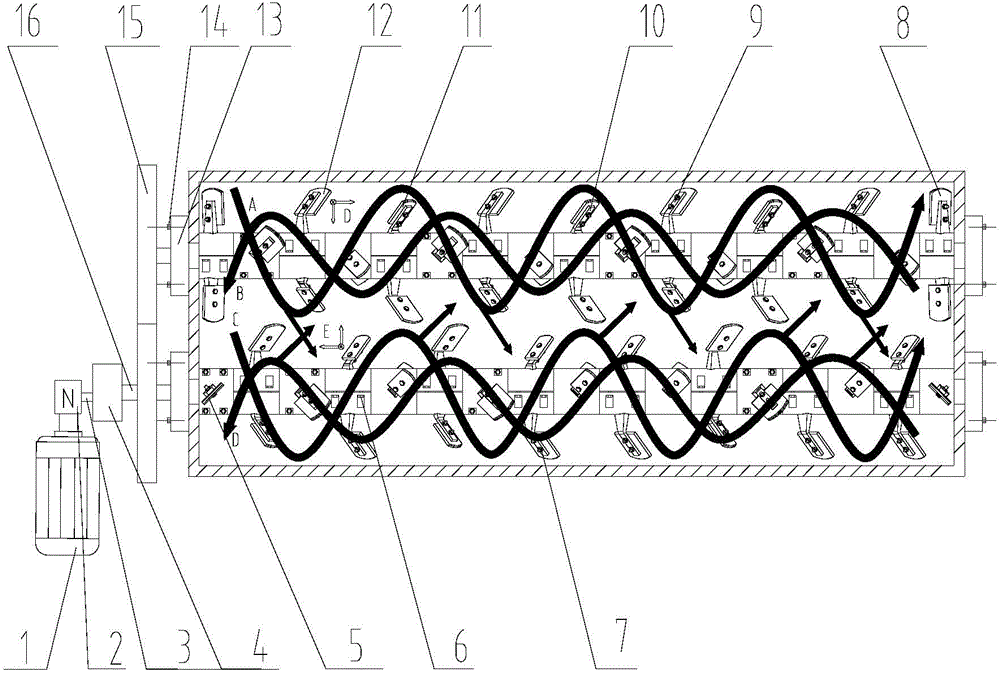
[0024] Such as Figures 1 to 3 As shown, the present invention has a twin-shaft continuous stirring device with opposed internal and external stirring units, including a frame 20 and a mixing drum 19 installed on the frame 20, a motor 1, a coupling 2 and a reduction box 4; Wherein, the left and right ends of the mixing drum 19 are respectively provided with a feed inlet and a discharge port; two parallel agitating shafts are respectively movably connected with the left and right side walls of the agitating drum 19, and the left ends of the two agitating shafts extend out to the stirring Outside the cylinder 19, the left end of the two stirring shafts is provided with an externally meshing synchronous gear 15, and each stirring shaft is provided with a number of external stirring units and internal stirring units at intervals from left to right; the output end...


PUM

PropertyMeasurementUnit
angleaaaaaaaaaa

Abstract

The invention discloses a double-horizontal-shaft continuous stirrer with oppositely arranged inner and outer stirring units. The double-horizontal-shaft continuous stirrer comprises a rack, a stirring cylinder, a motor, a coupler and a speed reduction box, wherein the stirring cylinder, the motor, the coupler and the speed reduction box are installed on the rack; the left end and the right end of the stirring cylinder are respectively provided with a material inlet and a material outlet; two parallelly arranged stirring shafts are respectively connected with the left and right side walls of the stirring cylinder movably, and the left ends of the two stirring shafts extend out of the outer side of the stirring cylinder, and are provided with a pair of externally meshed synchronous gears; each stirring shaft is provided with a plurality of outer stirring units and inner stirring units at intervals from left to right; an output end of the motor is connected with an input shaft of the speed reduction box by a coupler; the output shaft of the speed reduction box is connected with the left end of one of the stirring shafts. The double-horizontal-shaft continuous stirrer can prolong the stirring time of materials in a stirring machine under the conditions that the stirring length is not increased and the stirring speed is not reduced, and further the stirring uniformity is improved, and meanwhile, the material journal sticking phenomenon can be improved via the radial stirring motion between the inner and outer stirring units.

Description

Technical field: [0001] The invention belongs to the field of stabilized soil material mixers, and relates to a continuous stirring device, in particular to a twin-shaft continuous stirring device with opposed internal and external stirring units. Background technique: [0002] The twin-shaft mixer is a mixer type widely used in the field of construction engineering. There are two parallel stirring shafts in the mixer body. The stirring arms are fastened on the stirring shafts according to a certain arrangement, and the stirring blades are fastened according to a certain installation angle. on the stirrer arm. When the stirring shaft rotates, the material is forced to stir in the mixer through the rotating stirring blade. Twin-shaft mixers can be divided into two types: continuous type and batch type. Among them, when mixing stabilized soil materials, they are mostly continuous type mixers, which have the characteristics of continuous feeding, continuous mixing and continuo...

Claims


Application Information

Patent Timeline
Patent Type & Authority Applications(China)
IPC IPC(8): B28C5/14
CPCB28C5/146B28C5/148
Inventor 赵利军徐超蒋文志刘云飞
Owner CHANGAN UNIV
Why Eureka
Try Eureka