Cooling structure of cylinder block

a technology of cylinder block and cooling structure, which is applied in the direction of cylinders, mechanical equipment, machines/engines, etc., can solve the problems of reducing the flow speed of coolant, stagnating coolant, and insufficient cooling of the bore region adjacent to the boundary between the bore regions

Inactive Publication Date: 2005-10-06
TOYOTA JIDOSHA KK +1
View PDF5 Cites 21 Cited by
  • Summary
  • Abstract
  • Description
  • Claims
  • Application Information

AI Technical Summary

Benefits of technology

[0008] The invention is made in order to solve the aforementioned problem. It is an object of the invention to provide a cooling structure of a cylinder block, which makes it possible to uniformly cool the cylinder block.
[0010] In the cooling structure of a cylinder block that is thus configured, the area of the space between the bore wall and the water jacket spacer in the inter-bore region is smaller than the area of the space between the bore wall and the water jacket spacer in the region other than the inter-bore region. Therefore, in the inter-bore region, the flow speed of the coolant flowing between the water jacket spacer and the bore wall is increased. In general, as the flow speed is increased in a region, a cooling speed (a heat transfer amount per unit time) is increased in the region. Thus, it is possible to sufficiently cool the inter-bore region where heat is likely to be accumulated in a conventional case. Thus, it is possible to provide the cooling structure of a cylinder block, which makes it possible to uniformly cool the cylinder block.
[0012] In the cooling structure of a cylinder block that is thus configured, the contact area between the bore wall and the mainstream of the cooling medium in the inter-bore region is larger than the contact area between the bore wall and the mainstream of the cooling medium in the region other than the inter-bore region. Therefore, in the inter-bore region, a heat transfer area is increased. In general, a heat transfer amount is proportional to the heat transfer area. As the heat transfer area is increased, a larger amount of heat is transferred. Thus, it is possible to sufficiently cool the inter-bore region. As a result, it is possible to provide the cooling structure of a cylinder block, which makes it possible to uniformly cool the cylinder block.
[0014] In the cooling structure of a cylinder block that is thus configured, the coolant is actively guided to the boundary portion where heat is likely to be accumulated using the fin. Therefore, the boundary portion can be sufficiently cooled. As a result, it is possible to provide the cooling structure of a cylinder block, which makes it possible to uniformly cool the cylinder block.

Problems solved by technology

However, in the conventional cooling structure of a cylinder block, an inter-bore region which is positioned in the vicinity of a boundary between bore regions adjacent to each other is not sufficiently cooled.
This is thought to be because the flowing coolant has inertia, and therefore the coolant is not supplied to a sharply constricted portion between the bore regions at a sufficient flow rate, and the coolant stagnates in the inter-bore region.
Also, since a cross sectional area of a passage in the inter-bore region is large, a flow speed of the coolant is reduced in the inter-bore region, and therefore the inter-bore region is not sufficiently cooled.
That is, since the coolant is not supplied to the sharply constricted portion between the bore regions at a sufficient flow rate, the portion is not sufficiently cooled.

Method used


Image

  • Cooling structure of cylinder block
  • Cooling structure of cylinder block
  • Cooling structure of cylinder block

Examples


first embodiment

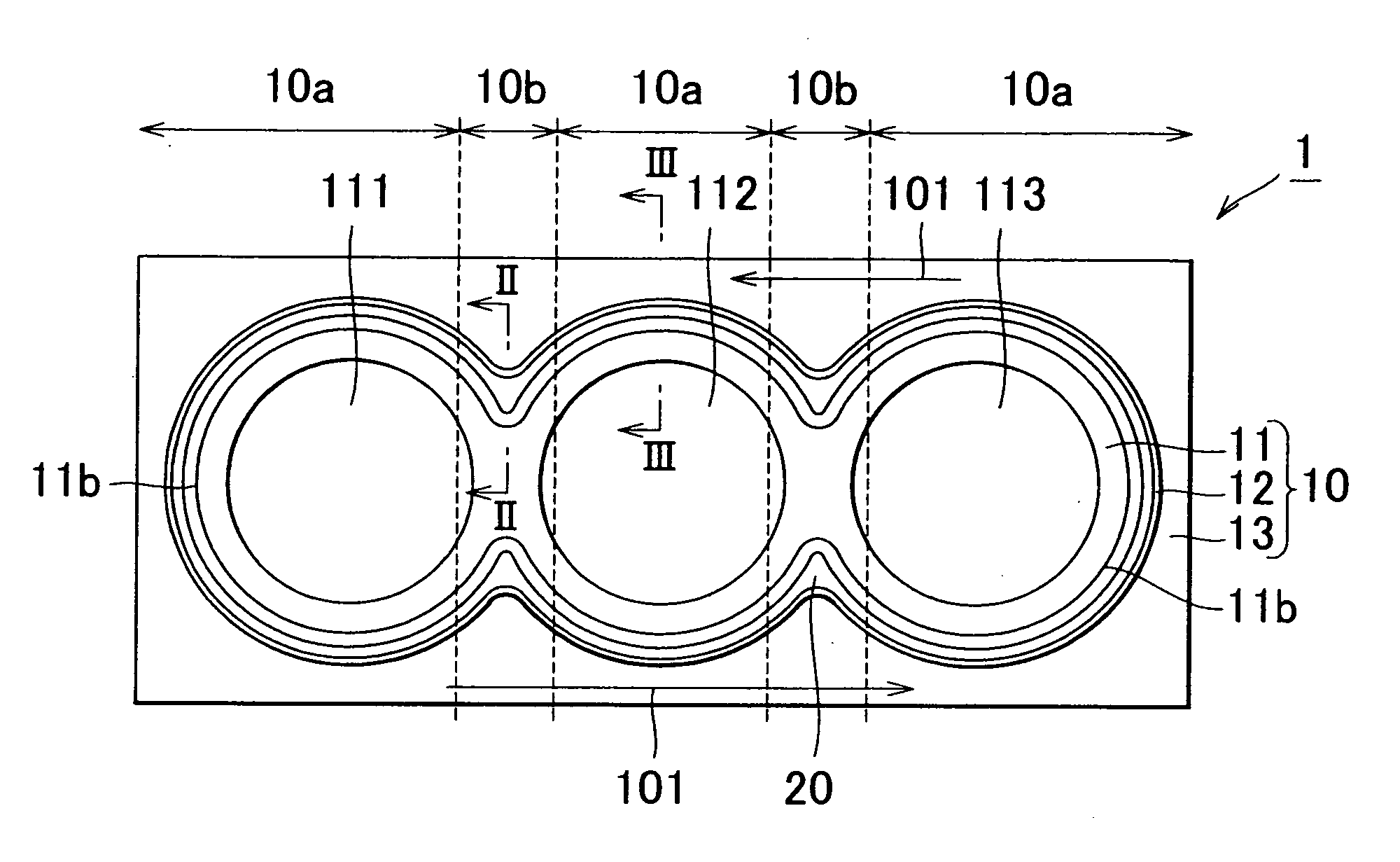
[0025]FIG. 1 is a plan view showing a cooling structure of a cylinder block according to the invention. As shown in FIG. 1, a cooling structure 1 of a cylinder block includes a water jacket portion 12 which is provided so as to surround an entire outer periphery of a bore wall 11b surrounding plural bore regions 111, 112, and 113; and a water jacket spacer 20 which is inserted in the water jacket portion 12 such that a space is provided between the bore wall 11b and the water jacket spacer 20. The temperature of the bore wall 11b is made uniform by supplying coolant which is a cooling medium to the water jacket portion 12. A cylinder block 10 includes inter-bore regions 10b each of which is positioned in the vicinity of a boundary between the bore regions adjacent to each other; and other regions 10a which are regions other than the inter-bore regions 10b. An area of a space between the bore wall 11b and the water jacket spacer 20 in the inter-bore region 10b is smaller than an area...

second embodiment

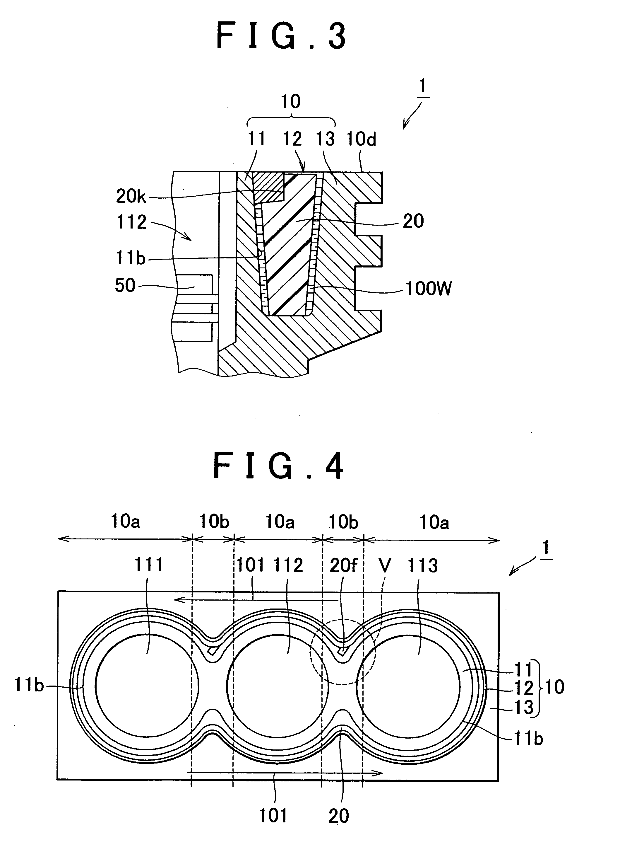
[0042] That is, in the second embodiment, the fin 20f for guiding the flow of the coolant to the inter-bore region 10 is provided in the water jacket spacer 20 on an upstream side of the inter-bore region 10. Thus, the area of the passage is substantially reduced, and cooling efficiency can be improved.

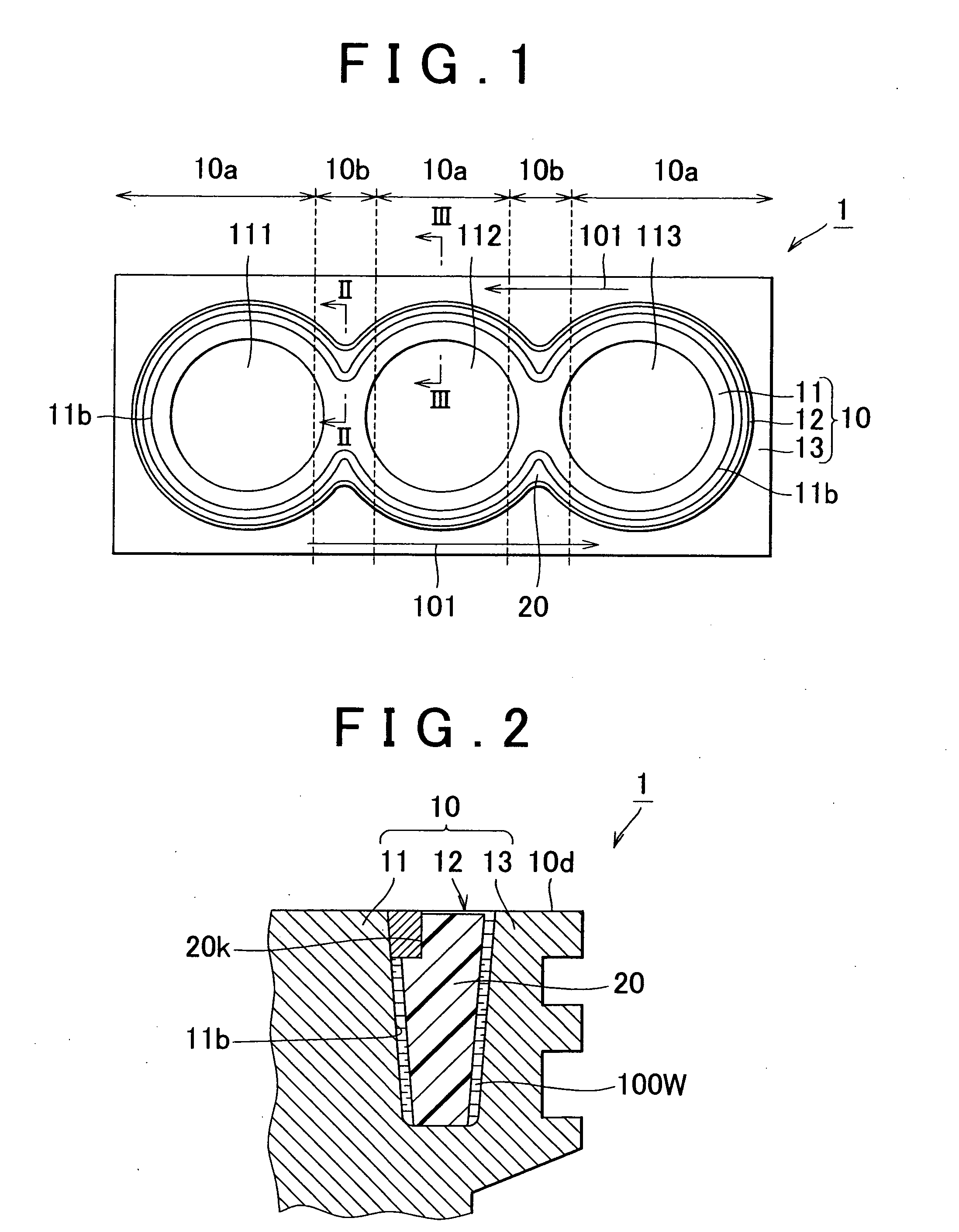
[0043]FIG. 6 is a plan view showing a cooling structure of a cylinder block according to a third embodiment of the invention. FIG. 7 is a cross sectional view taken along line VII-VII in FIG. 6. FIG. 8 is a cross sectional view taken along line VIII-VIII in FIG. 6. The cooling structure 1 of a cylinder block according to a third embodiment of the invention will be described with reference to FIG. 6 to FIG. 8. As shown in FIG. 7 and FIG. 8, a contact area between the coolant 100W and the bore wall 11b in the inter-bore region 10b is made larger than a contact area between the coolant 100W and the bore wall 11b in the other region 10a.

[0044] As described above, the heat transfer amount...

third embodiment

[0045] That is, the cooling structure 1 of a cylinder block according to the invention includes the water jacket portion 12 which is provided so as to surround an entire outer periphery of the bore wall 11b surrounding plural bore regions 111, 112, and 113; and a water jacket spacer 20 which is inserted in the water jacket portion 12 such that a space is provided between the bore wall 11b and the water jacket spacer 20. The temperature of the bore wall 11b is made uniform by supplying the coolant 100W that is the cooling medium to the water jacket portion 12. The cylinder block 10 includes the inter-bore regions 10b one of which is positioned in the vicinity of the boundary between the bore regions 111 and 112, and the other of which is positioned in the vicinity of the boundary between the bore regions 112 and 113; and other regions 10a which are regions other than the inter-bore regions 10b. The space between the bore wall 11b and the water jacket spacer 20 is provided such that t...


PUM


Abstract

A cooling structure for uniformly cooling a bore wall of a cylinder block using a cooling medium, the bore wall surrounding plural bore regions, includes a water jacket portion which is provided so as to surround an entire outer periphery of the bore wall, and which is supplied with the cooling medium; and a water jacket spacer which is inserted in the water jacket portion such that a space is provided between the bore wall and the water jacket spacer. The cylinder block includes an inter-bore region which is positioned in a vicinity of a boundary between the bore regions adjacent to each other, and a region other than the inter-bore region; and a cross sectional area of the space between the bore wall and the water jacket spacer in the inter-bore region is smaller than a cross sectional area of the space between the bore wall and the water jacket spacer in the region other than the inter-bore region.

Description

INCORPORATION BY REFERENCE [0001] The disclosure of Japanese Patent Applications No. 2004-103165 filed on Mar. 31, 2004, including the specification, drawings and abstract is incorporated herein by reference in its entirety. BACKGROUND OF THE INVENTION [0002] 1. Field of the Invention [0003] The invention relates to a cooling structure of a cylinder block, and more particularly to a cooling structure of a cylinder block, which makes it possible to uniformly cool the cylinder block. [0004] 2. Description of the Related Art [0005] A conventional cooling structure of a cylinder block is disclosed, for example, in Japanese Patent Laid-Open Publication No. 2002-30989. [0006] In the conventional cooling structure of a cylinder block disclosed in the Japanese Patent Laid-Open Publication No. 2002-30989, a temperature of a bore wall is made uniform in a circumferential direction of a bore by inserting a water jacket spacer which is separate from a cylinder block in a water jacket of the cyl...

Claims


Application Information

Patent Timeline
Patent Type & Authority Applications(United States)
IPC IPC(8): F02F1/14F01P3/02F02B75/18F02F1/10
CPCY02T10/16F02F1/108Y02T10/12
Inventor MATSUTANI, TAKASHINAKADA, TAKANORISHINPO, YOSHIKAZUHATANO, MAKOTOKUBOTA, TAKASHI
Owner TOYOTA JIDOSHA KK
Why Eureka
Try Eureka