Liquid crystal display device

A technology of liquid crystal display device and liquid crystal display panel, which is applied in the direction of identification device, nonlinear optics, optics, etc., can solve the problems of light leakage, display quality degradation, etc., and achieve the increase of electrical impedance, the improvement of display picture quality, and the possibility of electric corrosion Reduced effect

Active Publication Date: 2006-04-05
JAPAN DISPLAY INC
View PDF2 Cites 11 Cited by
  • Summary
  • Abstract
  • Description
  • Claims
  • Application Information

AI Technical Summary

Problems solved by technology

[0033] However, when the above-mentioned conventional liquid crystal display panels 10A and 10B are used, light leaks from between the light-shielding black matrix 22 and the cut surface of the glass.
Therefore, when the liquid crystal display device is viewed from an oblique direction, there is a problem that the leaked light degrades the display quality.

Method used


Image

  • Liquid crystal display device
  • Liquid crystal display device
  • Liquid crystal display device

Examples


Embodiment Construction

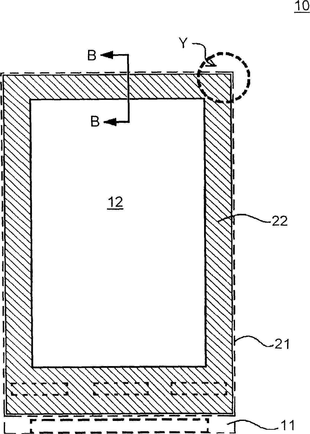
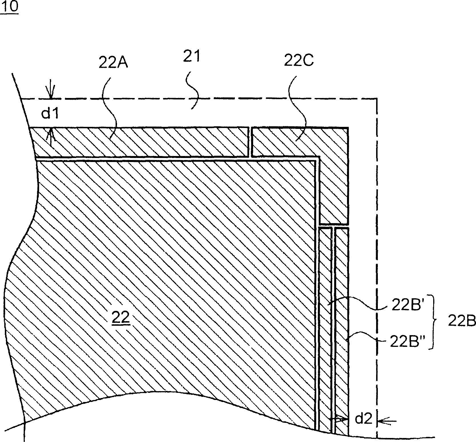
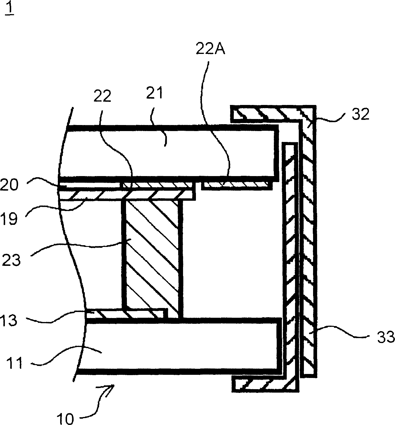
[0073] Hereinafter, taking a transmissive liquid crystal display device as an example, a preferred embodiment for implementing the present invention will be described with reference to the accompanying drawings. figure 1 is a plan view showing a liquid crystal display panel used in one example. figure 2 Yes figure 1 Enlarged view of section Y of . image 3 Yes means clamping with support frame figure 1 The state of the LCD panel is shown along the figure 1 Sectional view of B-B. exist figure 1 In the middle, a part of the second substrate that forms the display surface is shown in perspective. Also, for the convenience of description, the Figure 4-8 For the same parts as the shown examples of the prior art, the same symbols are used, and the description is omitted.

[0074] The liquid crystal display panel 10 has transparent first and second substrates 11 and 21 arranged to face each other. On the plane of the second substrate 21 facing the first substrate 11 , ...


PUM


Abstract

In a liquid crystal display apparatus having a backlight disposed behind a liquid crystal display panel 10 , the liquid crystal display panel 10 has first and second substrates 11 and 21 disposed to face each other. The second substrate 21 has a common electrode 20 laid in a display area 12 thereon. The second substrate 21 further has a light-shielding inner black matrix 22 laid around the display area 12 and a light-shielding electrically insulated black matrix 22 A, 22 B, and 22 C laid outside the inner black matrix 22 and electrically separated from the inner black matrix 22 and the common electrode 19 . The liquid crystal display panel 10 is held, at the periphery thereof, by metal support frames 32 and 33.

Description

technical field [0001] The present invention relates to a liquid crystal display device, and more particularly, to a liquid crystal display device having a light-shielding black matrix (BM) at an edge portion of a liquid crystal display panel. Background technique [0002] The liquid crystal display panel is formed by arranging two transparent substrates on which electrodes and the like are formed facing each other, and bonding the periphery of the transparent substrates with a sealing material. The liquid crystal is encapsulated in the space formed by the transparent substrate and the sealing material. For example, in the case of an active matrix-driven liquid crystal display panel, signal lines and scanning lines are arranged in a matrix on one substrate. A thin film transistor is formed near the intersection of the signal line and the scanning line, and a pixel electrode connected to the thin film transistor is formed in the region surrounded by the signal line and the s...

Claims


Application Information

Patent Timeline
Patent Type & Authority Applications(China)
IPC IPC(8): G09F9/00G09F9/35
CPCG02F1/133308G02F1/133615G02F1/133608G02F1/133512G02F1/1335G02F1/1345
Inventor 荒松义明小林修
Owner JAPAN DISPLAY INC
Why Eureka
Try Eureka