Eureka AIR delivers breakthrough ideas for toughest innovation challenges, trusted by R&D personnel around the world.

Truck fuel tank

A technology for fuel tanks and trucks, applied in the field of truck manufacturing, can solve problems such as waste of remaining fuel in the fuel tank and engine stall, and achieve the effects of reducing potential safety hazards, improving service life, and achieving fluency and installation convenience.

Inactive Publication Date: 2013-08-14
CNHTC CHENGDU WANGPAI COMML VEHICLE
View PDF3 Cites 1 Cited by
  • Summary
  • Abstract
  • Description
  • Claims
  • Application Information

AI Technical Summary

Problems solved by technology

[0003] The present invention overcomes the deficiencies of the prior art and proposes a new fuel tank structure for trucks, which solves the problems of engine flameout caused by intake air in the oil supply circuit and excessive waste of remaining fuel in the fuel tank when the vehicle is running on uneven roads and curves

Method used


Image

  • Truck fuel tank

Examples


Embodiment Construction

[0025] The present invention will be further explained below in conjunction with the drawings.

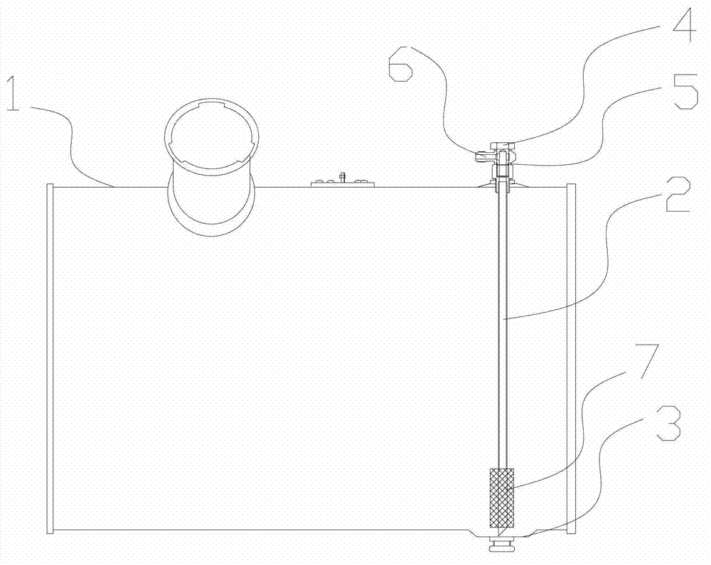
[0026] Such as figure 1 As shown, a fuel tank for a truck includes a fuel tank 1 and a fuel suction pipe 2. The fuel suction pipe 2 is arranged inside the fuel tank 1, and the bottom of the fuel tank 1 is provided with at least one groove 3, the groove 3 The number provided is the same as the number of the oil suction pipe 2. The two ends of the oil suction pipe 2 are the oil suction end and the oil discharge end respectively. The oil suction end extends out of the bottom plane of the fuel tank 1 and is arranged in the groove 3. The oil outlet extends out of the upper part of the fuel tank 1 and the oil outlet is provided with an articulated bolt joint 4, the articulated bolt joint 4 can rotate freely, and the number of the articulated bolt joints 4 is the same as that of the oil suction pipe 2. . In addition, the oil suction pipe 2 is hermetically connected to the fuel tank 1 throu...


PUM


Abstract

The invention discloses a truck fuel tank which comprises a fuel tank and a suction pipe. The suction pipe is disposed inside the fuel tank. The truck fuel tank is characterized in that the bottom of the fuel tank is provided with at least one groove, two ends of the suction pipe are provided with a suction end and a discharge end, the suction end is disposed in one groove, the discharge end is provided with a hinge bolt connector, and the suction pipe is hermetically connected with the fuel tank through the hinge bolt connector. The truck fuel tank has the advantages that through length change of the suction pipe and the structure of the hinge bolt connector, smooth fuel supply and convenient installation are achieved, safety of vehicles running on uneven roads and curves is improved, and production truck economy is improved.

Description

Technical field [0001] The invention relates to the technical field of the truck manufacturing industry, in particular to a truck fuel tank structure. Background technique [0002] At present, the metal fuel tank structure commonly used in the technical field of trucks is a common fuel tank structure in which the bottom surface of the fuel tank is flat and the nozzle of the suction pipe is above the bottom surface. It mainly includes fuel tank structure and fuel suction pipe structure. Specifically, the bottom surface of the fuel tank adopts a flat structure, the suction pipe is directly connected to the right-angle elbow joint by welding, and the elbow joint is connected to the fuel tank by threads. In the practical application of the above-mentioned structure, the remaining amount of fuel in the fuel tank is relatively large, especially when the vehicle is running on uneven roads and corners, fuel supply and air intake will occur, causing the engine to stall. In addition, the...

Claims


Application Information

Patent Timeline
Patent Type & Authority Applications(China)
IPC IPC(8): B60K15/077
Inventor 王亮
Owner CNHTC CHENGDU WANGPAI COMML VEHICLE
Why Eureka
Eureka Blog
Learn More