

Ring Pipeline
An assembly line and annular technology, applied in conveyors, mechanical conveyors, transportation and packaging, etc., can solve the problems of low labor efficiency, cumbersome, and many processing steps, and achieve the effect of improving work efficiency.
- Summary
- Abstract
- Description
- Claims
- Application Information
AI Technical Summary
Problems solved by technology
Method used
Image

Examples
Embodiment Construction
[0025] In order to make the technical means, creative features, goals and effects achieved by the present invention easy to understand, the present invention will be further described below in conjunction with specific illustrations.
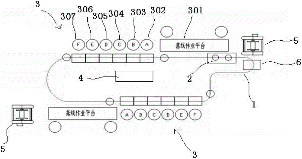
[0026] refer to figure 2 and image 3 As shown, the circular assembly line includes: a straight track, the bend of the straight track is transitionally connected by a horizontal curved rail, the linear track and the horizontal curved rail form a closed main frame of the circular assembly line,
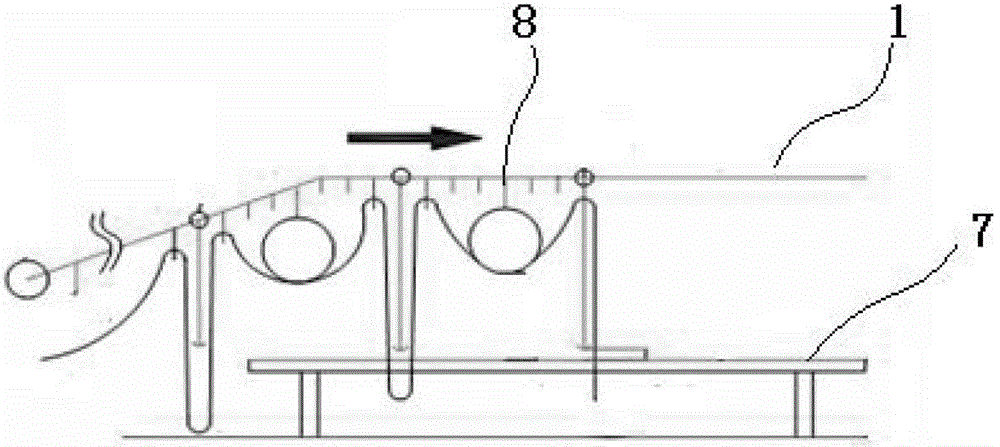
[0027] A desktop 7 is arranged above the main frame of the circular assembly line, and a transmission chain 1 is slidably arranged above the desktop 7. The transmission chain 1 is driven by the driving device 2, and the cables are transmitted to at least two groups of operating platforms on the circular assembly line through the transmission chain 1. 3.
[0028] In a preferred embodiment of the present invention, each group of operating platforms 3 in...
PUM
 Abstract
Description
Claims
Application Information