Light-emitting diode (LED) light source and lighting device with same

A technology of LED light source and lighting device, applied in the field of LED light source, can solve the problems of complex lens processing, reduction of light intensity in the central area of ​​light, blurred edge of light spot, etc.

Inactive Publication Date: 2013-08-14
OSRAM GMBH
View PDF0 Cites 0 Cited by
  • Summary
  • Abstract
  • Description
  • Claims
  • Application Information

AI Technical Summary

Problems solved by technology

But this solution will also reduce the efficiency of the generated light and the light intensity in the central area, and the edges of the generated light spots will be blurred
In addition, the processing of this lens is very complicated

Method used


Image

  • Light-emitting diode (LED) light source and lighting device with same
  • Light-emitting diode (LED) light source and lighting device with same
  • Light-emitting diode (LED) light source and lighting device with same

Examples


Embodiment Construction

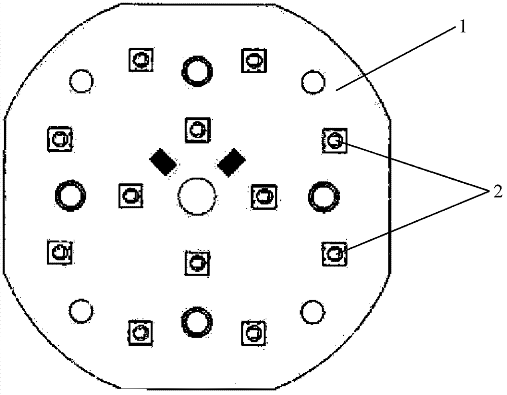
[0019] figure 1 A schematic diagram of an LED light source according to the prior art is shown. It can be seen from the figure that the LED light source includes a printed circuit board 1 and a plurality of LED chips 2 arranged on the printed circuit board 1 , and these LED chips 2 are arranged in two concentric rings on the printed circuit board 1 .

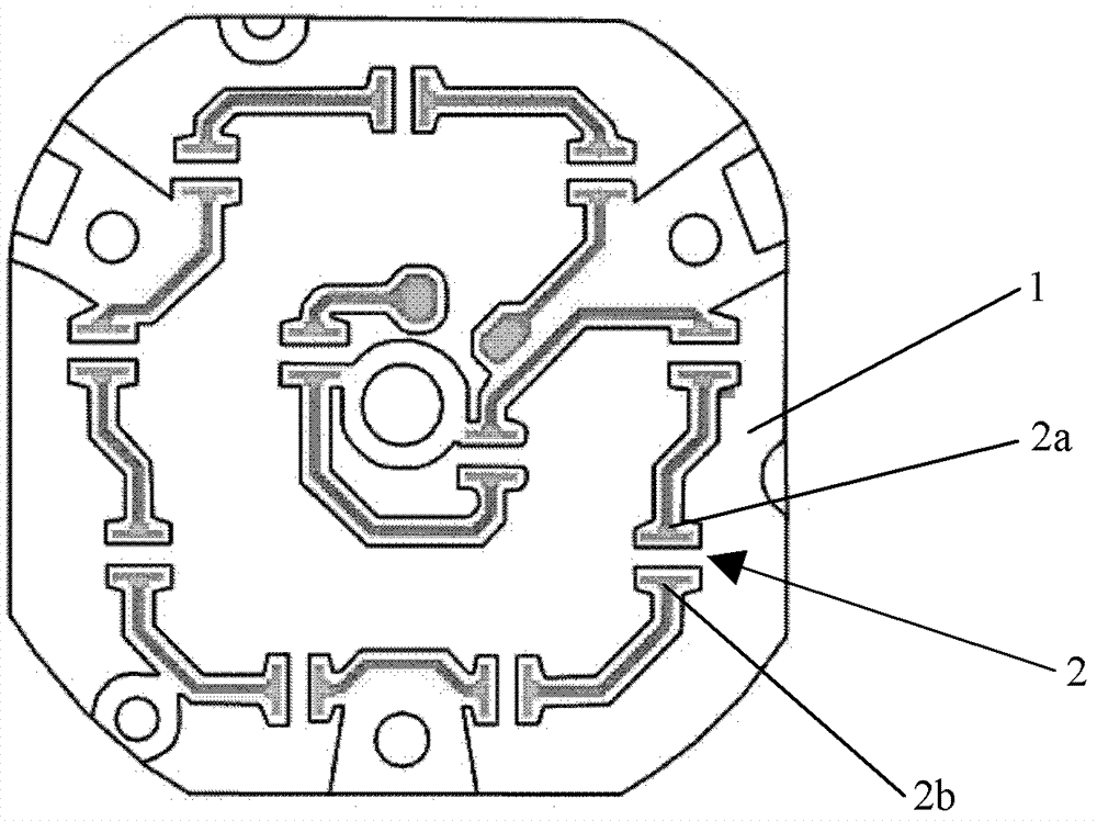
[0020] figure 2 It shows a schematic diagram of the LED chip 2 of the LED light source according to the prior art after the encapsulation is removed. It can be seen from the figure that the LED chip includes a positive pin 2a and a negative pin 2b, wherein the positive pin 2a of one LED chip 2 is connected to the negative pin of an adjacent LED chip, so that these LED chips are connected in series. In addition, the direction from the positive pin 2 a to the negative pin 2 b of the LED chip 2 is set as the arrangement direction of the LED chip 2 . The LED chips 2 shown in the figure adopt two arrangement directions, wherein t...


PUM


Abstract

The present invention relates to an LED light source for an illuminating device, comprising a printed circuit board (1) and at least three LED chips (2) arranged on the printed circuit board (1), the LED chip (2) having a positive plug (2a) and a negative plug (2b), wherein disposing directions of the respective LED chips are different from one another, and wherein the disposing direction is the direction from the positive plug (2a) to the negative plug (2b) of the LED chip (2) or the direction from the negative plug (2b) to the positive plug (2a) of the LED chip (2). In addition, the present application further relates to an illuminating device comprising an LED light source of the above mentioned type.

Description

technical field [0001] The invention relates to an LED light source. In addition, the present invention also relates to an illuminating device having the above-mentioned type of LED light source. Background technique [0002] With the development of technology, the LED package itself can achieve higher efficiency, for example, it can obtain 140lm / W cool white light and 90lm / W warm white light, and its life span can reach 50,000 hours. Therefore, people are more and more willing to use LED light sources. However, the power of a single LED chip itself is not high, so people usually integrate multiple LED chips into a circuit board to use as a light source. However, since each LED chip produces a light spot, the light spots jointly produced by multiple LED chips do not look very uniform after being assembled together. To this end, designers equip the light source with a lens that collimates the light emitted by the LED chip. But this can cause some imaging problems, that is...

Claims


Application Information

Patent Timeline
Patent Type & Authority Applications(China)
IPC IPC(8): F21S2/00F21V19/00F21Y101/02
CPCH01L25/0753F21Y2105/001F21K9/00F21Y2101/02F21Y2105/10F21Y2105/12F21Y2115/10H01L2924/0002H01L2924/00
Inventor 李爱爱程雄杰卢元罗亚斌
Owner OSRAM GMBH
Why Eureka
Try Eureka