
Depth-control drill test device and test method for PCB (printed circuit board)

A technology for PCB board and drilling inspection, applied in measuring devices, optical devices, instruments, etc., can solve the problems of difficult monitoring, instability, and inability to detect drilling depth.

Active Publication Date: 2013-08-14
SHENNAN CIRCUITS
View PDF4 Cites 10 Cited by
  • Summary
  • Abstract
  • Description
  • Claims
  • Application Information

AI Technical Summary

Problems solved by technology

[0004] In the process of implementing the present invention, the inventor found that the existing depth control drilling depth inspection method has the following disadvantages: the depth control accuracy of drilling equipment is affected by multiple factors, and the accuracy of the equipment itself decreases as the use time becomes longer. Gradually descending and unstable, the flatness of the table surface of the drilling equipment also has a great influence on the accuracy of drilling depth control, and the method of slicing or using the depth gauge to conduct random inspection of the drilling cannot measure all drilling depths. Inspection, if the depth of individual holes is out of tolerance due to the unevenness of the table surface, it is difficult to effectively monitor the existing detection methods

Method used


Image

  • Depth-control drill test device and test method for PCB (printed circuit board)
  • Depth-control drill test device and test method for PCB (printed circuit board)

Examples


Embodiment Construction

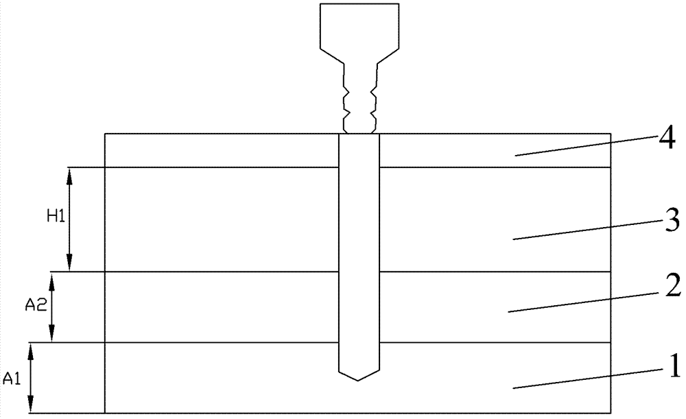
[0014] figure 1 It is a structural diagram of the PCB board depth-controlled drilling inspection device of the present invention. As shown in the figure, the PCB board depth control drilling inspection device of the present invention includes a first backing plate 1 , a second backing plate 2 , a third backing plate 3 and a cover plate 4 which are sequentially stacked from bottom to top. Wherein, the thickness of the third backing plate 3 is H1=H-3a, the thicknesses of the first backing plate 1 and the second backing plate 2 are A1, A2 respectively, and A1=A2=2a, wherein, H is the preset diamond Hole depth, a is the maximum tolerance value allowed, if the drilling error exceeds ±a, it means that the drilling is unqualified. The inspection device can simultaneously inspect all depth-controlled drilling holes with the same preset depth.

[0015] During the production process of the PCB board, the cover plate 4 is used to cover the upper surface of the PCB board during deep dri...


PUM


Abstract

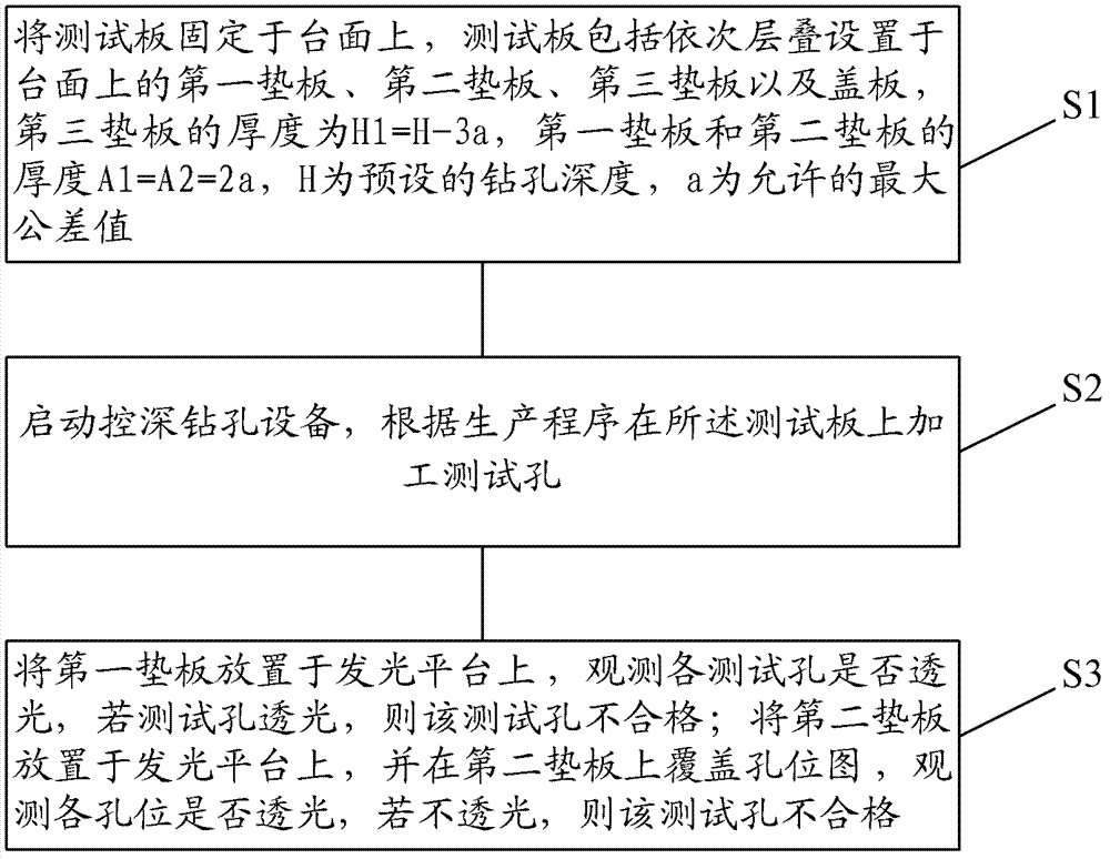
The invention discloses a depth-control drill test device and test method for a PCB. The device and the method are characterized in that a test plate is fixed on a drill table-board, and comprises a first backing board, a second backing board, a third backing board and a cover plate which are stacked sequentially; the thickness H 1 of the third backing board is a difference subtracting 3a from H, both the thickness A1 of the first backing board and the thickness A2 of the second backing board are equal to 2a, H is a preset hole depth, and a is a tolerance value; test holes are processed in the test plate; the first backing board is placed on a luminous platform, whether each test hole is light-transmitting is observed, and if yes, the test hole is disqualified; and the second backing board is placed on the luminous platform, the second backing board is covered with a hole site map, whether each hole site is light-transmitting is observed, and if not, the test hole corresponding to the hole site is disqualified. The test method provided by the invention can confirm that whether the depth-control accuracy of all holes meets requirements simply and effectively through the light-transmitting tests of the first backing board and the second backing board, and the test for various types of depth-control accuracy can be achieved through using backing boards with different thicknesses.

Description

technical field [0001] The invention relates to the field of PCB board processing, in particular to a PCB board depth-controlled drilling inspection device and inspection method. Background technique [0002] In the controlled depth drilling process of PCB boards, after setting the controlled depth drilling parameters, the drilling depth of the first workpiece processed by the controlled depth drilling is usually inspected to determine whether it is necessary to adjust the set controlled depth. Deep drilling parameters and drilling equipment, etc. [0003] At present, the industry usually adopts the following two inspection methods: The first method is to conduct a controlled depth test drill in the non-graphic area of ​​the PCB board, and take a slice to measure the drilling depth under a microscope. The second way is to test drill in a PCB board, drill a hole in each of the four corners and the middle of the PCB board, and then use the depth gauge to detect the depth of t...

Claims


Application Information

Patent Timeline
IPC IPC(8): G01B11/22
Inventor 韩雪川
Owner SHENNAN CIRCUITS
Learn More