Input device

A technology of input devices and transparent electrodes, applied in the input/output process of data processing, instruments, electrical digital data processing, etc., can solve the problem of no open structure, achieve low resistance improvement, good environmental resistance, To achieve the effect of tightness

Active Publication Date: 2013-08-14
ALPS ALPINE CO LTD
View PDF9 Cites 10 Cited by
  • Summary
  • Abstract
  • Description
  • Claims
  • Application Information

AI Technical Summary

Problems solved by technology

[0018] In this way, the bridge wiring is made of ITO or a metal layer, and the structure in which these layers are stacked is a known structure. However, in the inventions described in Patent Documents 1 to 4, a In the case of Cu, Cu alloy, or Ag alloy, it is possible to achieve good invisibility, ensure adhesion to the insulating layer, improve environmental resistance (high temperature environment, high temperature and high humidity environment), and withstand electrostatic breakdown. There is no disclosure of the structure of the input device of the improved bridge wiring

Method used


Image

  • Input device
  • Input device
  • Input device

Examples


Embodiment Construction

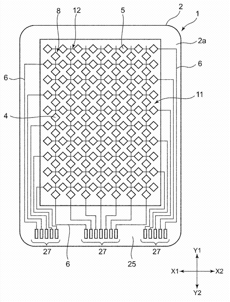
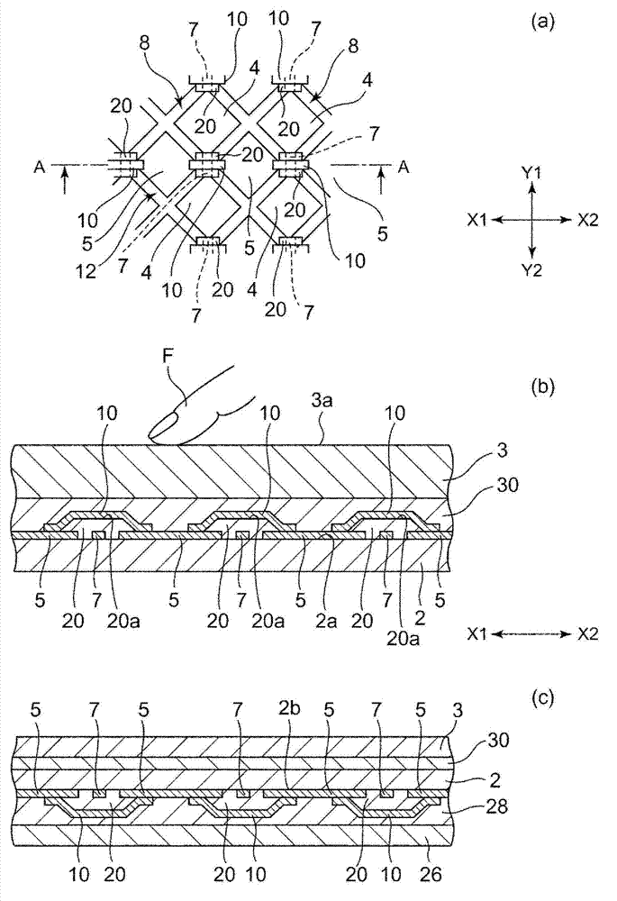
[0056] figure 1 It is a plan view showing each transparent electrode and wiring part formed on the surface of the transparent substrate constituting the input device (touch panel) in this embodiment, figure 2 (a) is figure 1 An enlarged top view of the input device shown, figure 2 (b) is to figure 2 (a) Partially enlarged longitudinal sectional view of the input device when viewed from the direction of the arrow cut along A-A, figure 2 (c) is with figure 2 (b) Partially enlarged longitudinal cross-sectional view of partially different input devices.

[0057] In addition, in this specification, "transparency" and "transparency" refer to the state in which the visible light transmittance is 50% or more (preferably 80% or more). Furthermore, a haze value of 6 or less is optimal.

[0058] It should be noted that, in figure 1 In the figure, the respective transparent electrodes 4, 5 and the wiring portion 6 formed on the surface (first surface) 2a of the transparent sub...


PUM

PropertyMeasurementUnit
thicknessaaaaaaaaaa

Abstract

The present invention aims to provide an input device which can ensure an excellent invisibility characteristic when Cu, Cu alloy or Ag alloy is adopted as low-resistance metal and can improve environmental resistance or electrostatic damage tolerance of a bridge wiring. The input device is provided with the following components: a transparent substrate (2); a plurality of transparent electrodes (5) which are formed on the first surface of the transparent substrate (2); the bridge wiring (10) for electrically connecting the transparent electrodes (5); and an insulating layer (20) which is formed between the transparent substrate (2) and the bridge wiring (10). The bridge wiring (10) has a structure in which a substrate layer 35 composed of non-crystal ITO, a metal layer 40 composed of Cu alloy or Ag alloy and a conductive oxide protection layer 37 composed of non-crystal ITO are successively laminated from the surface side of the laminating layer.

Description

technical field [0001] The present invention relates to an input device capable of detecting an operation position of an operation surface, and more particularly to a structure of a bridge wiring connecting transparent electrodes formed on a surface of a transparent substrate. Background technique [0002] Patent Document 1 discloses an input device in which bridge wires (referred to as intersecting portions and relay electrodes in Patent Document 1) electrically connecting a plurality of transparent electrodes are formed of ITO. [0003] In addition, Patent Document 2 discloses an input device in which bridge wires electrically connecting a plurality of transparent electrodes (referred to as bridge wires in Patent Document 2) are formed of Mo, Al, Au, or the like. [0004] In addition, Patent Document 3 describes that a bridge wiring (described as a conductive member in Patent Document 3) that electrically connects a plurality of transparent electrodes is made of a single l...

Claims


Application Information

Patent Timeline
Patent Type & Authority Applications(China)
IPC IPC(8): G06F3/041
CPCG06F3/044G06F2203/04111H01B5/14
Inventor 竹内正宜佐藤清矢泽学铃木彻也牛肠英纪青木大悟
Owner ALPS ALPINE CO LTD
Why Eureka
Try Eureka