
Windage-yaw prevention insulating spacer

A technology for insulating intervals and preventing wind deflection. It is applied to devices for maintaining the distance between parallel conductors and mechanical vibration attenuation devices. It can solve problems such as regular maintenance, mixing of transmission and distribution lines, and easy crushing of wires, so as to reduce maintenance and rush repairs. cost, ensure safe and stable operation, and facilitate installation

Active Publication Date: 2013-08-14
STATE GRID CORP OF CHINA +2
View PDF10 Cites 4 Cited by
  • Summary
  • Abstract
  • Description
  • Claims
  • Application Information

AI Technical Summary

Problems solved by technology

When encountering strong winds or short-circuit faults at the lower end of the line (electrodynamic action), etc., the transmission and distribution lines will be mixed and matched, causing phase-to-phase short-circuit faults, affecting the normal operation of the power grid, and causing direct economic losses to society and people's property.
In response to this situation, methods such as shortening the line span, increasing the distance between lines, and adjusting the sag are generally adopted. This method requires large investment, large engineering volume, and long construction period, and is even restricted by the influence of the geographical environment.
[0003] With the development of science and technology, many kinds of windproof insulation spacers have appeared in the current power line technology. These windproof insulation spacers are highly targeted, complex in structure, fixed in length and difficult to adjust, and generally fixed by bolts. Regular maintenance, easy to crush the wire

Method used


Image

  • Windage-yaw prevention insulating spacer
  • Windage-yaw prevention insulating spacer
  • Windage-yaw prevention insulating spacer

Examples


Embodiment 1

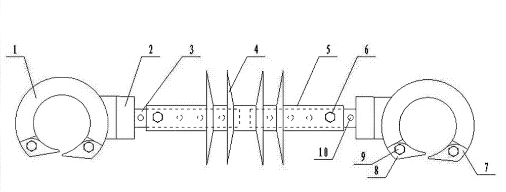
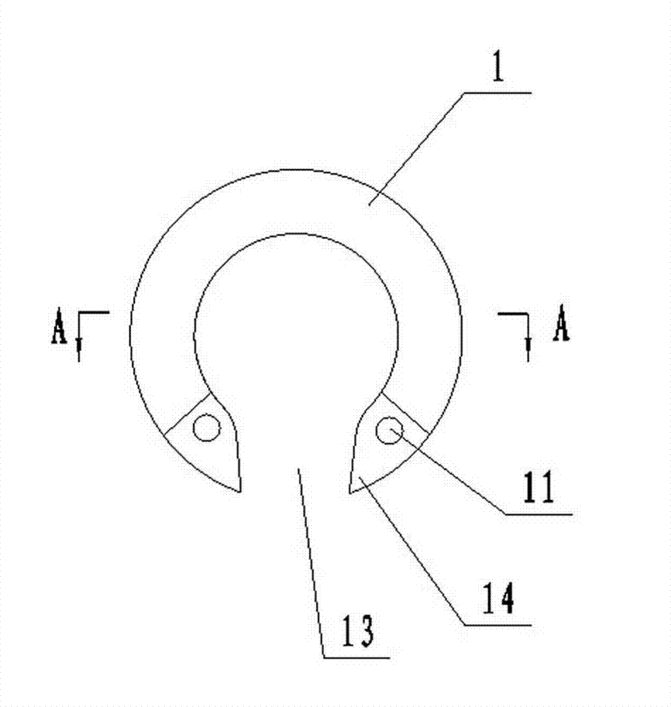
[0018] Embodiment 1: by Figure 1 to Figure 6 It can be seen that the windproof bias insulation spacer includes an insulating sleeve 5, and the insulating sleeve 5 is provided with a silicone insulating umbrella 4 at intervals, and is also provided with 2 fixed wire clamps 1, and the two ends of the insulating sleeve 5 pass through the insulating shaft 3 respectively. Connected to the two fixed wire clamps 1, the two fixed wire clamps 1 are provided with lower openings 13, and the two fixed wire clamps 1 are also provided with wire automatic opening and locking mechanisms.

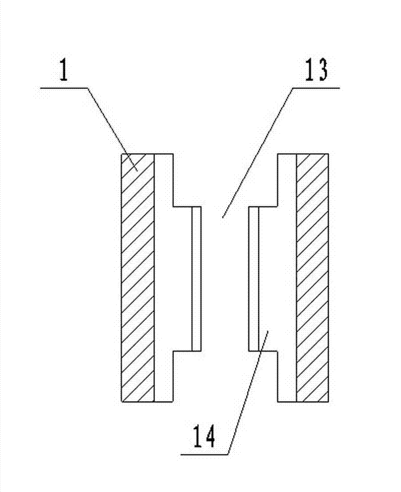
[0019] The structure of the wire automatic opening and locking mechanism is: both ends of the lower opening 13 of the fixed wire clamp 1 are provided with a boss 14 with a slope, and the boss 14 is provided with a first connecting hole 11 , the corresponding positions of the first fixed guide plate 7 and the second fixed guide plate 8 are provided with a second connection hole 12, and the fixed wire clamp ...

Embodiment 2

[0026] Embodiment 2: The automatic opening and locking mechanism is provided with only one fixed guide plate, and the length of the fixed guide plate is correspondingly lengthened so that it can be overlapped on the opposite boss 14, specifically: the fixed guide plate and the fixed wire clamp 1 lower opening A boss 14 of 13 is movably connected by bolts, and after lead is put into from lower opening 13, the fixed guide plate rotates automatically, overlaps on the boss 14 on the opposite side, reaches automatic opening and locking.


PUM


Abstract

The invention discloses a windage-yaw prevention insulating spacer, and relates to the technical field of electric power transmission line erection. The spacer comprises an insulating sleeve and two lead fixing clamps, wherein silica gel insulating umbrellas are arranged at intervals on the insulating sleeve; two ends of the insulating sleeve are connected with the two fixed lead clamps through insulating shafts respectively; each of the two fixed lead clamps is provided with a lower opening; and automatic lead opening and closing mechanisms are arranged on the two fixed lead clamps. The insulating spacer is simple in structure and good in insulating effect, leads can be placed very conveniently from lower openings of the fixed lead clamps through special tools on the ground, the installation is convenient and rapid, the operation is easy, time and labor are saved, and short-circuit faults caused by factors such as strong wind, frost, snow and rain, electrodynamic force and the like can be effectively avoided.

Description

technical field [0001] The invention relates to the technical field of power transmission line erection. Background technique [0002] In the power system, 10kV and 35kV transmission and distribution lines are important components of the power supply system, which undertake the important task of transmitting electric energy and directly affect the safe operation of the power grid. When encountering strong winds or short-circuit faults at the lower end of the line (electrodynamic action), the transmission and distribution lines will be mixed, resulting in phase-to-phase short-circuit faults, affecting the normal operation of the power grid, and causing direct economic losses to society and people's property. In response to this situation, methods such as shortening the line span, increasing the distance between lines, and adjusting the sag are generally used. This method requires a large investment, a large amount of engineering, a long construction period, and is even restri...

Claims


Application Information

Patent Timeline
IPC IPC(8): H02G7/12H02G7/14
Inventor 申利军
Owner STATE GRID CORP OF CHINA
Learn More