Load drive circuit capable of protecting surge current

A technology of load driving circuit and inrush current, applied in emergency protection circuit devices, emergency protection circuit devices for limiting overcurrent/overvoltage, lamp circuit layout, etc., can solve the problem of affecting the service life of the current balance circuit 145 and failing to Static test specifications, low product reliability and other issues

Inactive Publication Date: 2013-08-14
GREEN SOLUTION TECH CO LTD
View PDF5 Cites 1 Cited by
  • Summary
  • Abstract
  • Description
  • Claims
  • Application Information

AI Technical Summary

Problems solved by technology

This may cause the actual breakdown voltage of the transient voltage suppressor to be close to the withstand voltage of the current balance circuit 145, so that when electrostatic discharge occurs, the current balance circuit 145 also temporarily exceeds the withstand voltage and affects the

Method used


Image

  • Load drive circuit capable of protecting surge current
  • Load drive circuit capable of protecting surge current
  • Load drive circuit capable of protecting surge current

Examples


Embodiment Construction

[0054] Both the above summary and the following detailed description are exemplary, and are intended to further illustrate the claims of the present invention. Other purposes and advantages of the present invention will be described in the subsequent description and accompanying drawings.

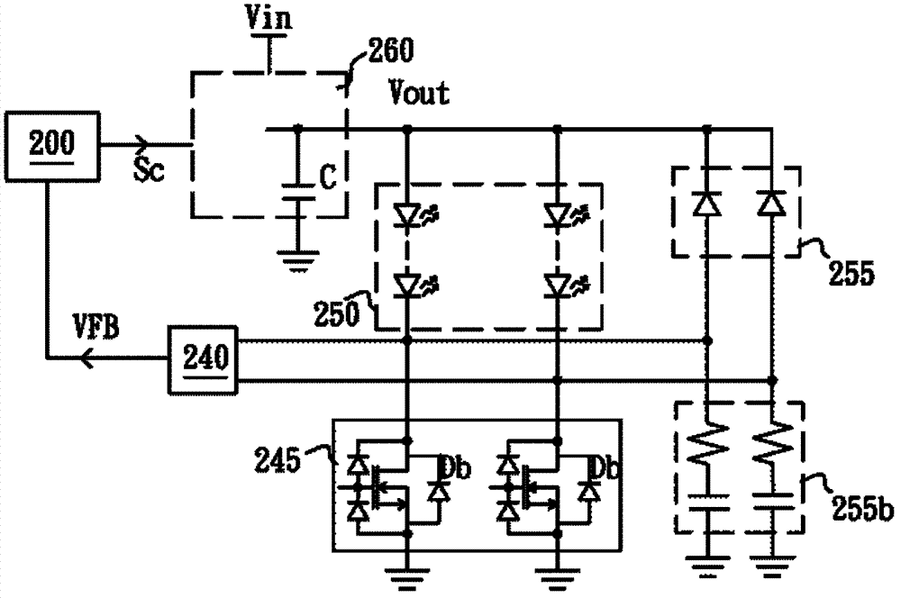
[0055] See image 3, is a schematic circuit diagram of a load driving circuit with inrush current protection according to a first preferred embodiment of the present invention. The load driving circuit includes a conversion circuit 260 , a conversion controller 200 , a load regulator 245 and an inrush current protection circuit 255 . The conversion circuit 260 is coupled to an input power supply Vin and provides a driving power supply Vout at an output terminal to drive a load 250, wherein the conversion circuit 260 has an output capacitor C coupled to the output terminal of the conversion circuit 260 to stabilize the conversion circuit 260 Output. The conversion circuit 260 can be a com...


PUM


Abstract

The invention discloses a load drive circuit capable of protecting surge current, which comprises a switching circuit, a conversion controller, a load drive adjuster and a surge current protective circuit, wherein the switching circuit is used for being coupled with an input power, and providing a driving power for driving a load at an output end; an output capacitor of the switching circuit is coupled with the output end; the conversion controller controls the size of the driving power provided by the switching circuit according to current or voltage of the load; the load drive adjuster is connected with the load in series at the output end of the switching circuit for regulating and controlling the electrical property state of the load; and the surge current protective circuit is coupled with a link point between the load drive adjuster and the load and the output capacitor so as to provide a one-way electric charge conduction path for the output capacitor.

Description

technical field [0001] The invention relates to a load drive circuit with surge current protection, especially a load drive circuit with capacitor as surge current protection. Background technique [0002] See figure 1 , is a schematic circuit diagram of a traditional light-emitting diode driving circuit. The LED driving circuit includes a conversion controller 100 , a boost conversion circuit 160 , an output capacitor C, an LED module 150 , a minimum voltage selection circuit 140 and a current balance circuit 145 . The boost conversion circuit 160 is a DC-to-DC boost conversion circuit, including an inductor L, a switch SW and a rectification component D, one end of the inductor L is coupled to an input power supply Vin, and the other end is coupled to one end of the switch SW; The other end of the changeover switch SW is grounded. The positive terminal of the rectifier component D is coupled to the connection point of the inductor L and the switching switch SW, and the ...

Claims


Application Information

Patent Timeline
IPC IPC(8): H02H9/04H02H9/02H05B37/02
Inventor 李立民刘中唯余仲哲徐献松
Owner GREEN SOLUTION TECH CO LTD
Why Eureka
Try Eureka