

LED lighting apparatus and dimming method thereof
A technology of light-emitting diodes and lighting devices, applied in the field of lighting circuits and lighting devices with them
- Summary
- Abstract
- Description
- Claims
- Application Information
AI Technical Summary
Problems solved by technology
Method used
Image

Examples
no. 1 example
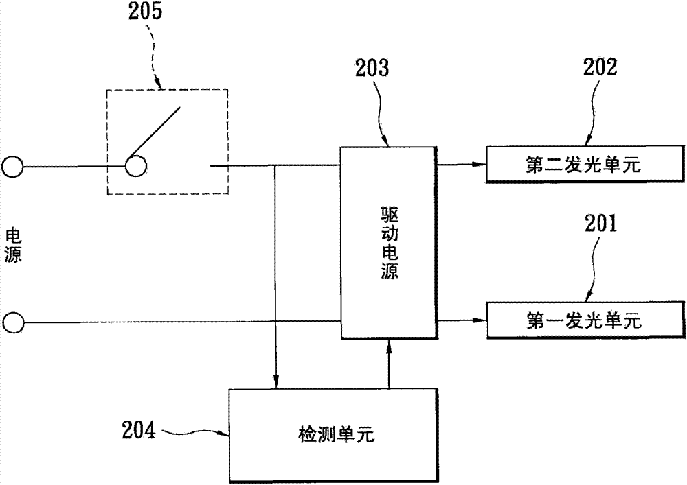
[0058] figure 2 It is a circuit block diagram of the LED lighting device according to the first embodiment of the present invention. Please refer to figure 2 , the LED lighting device includes a first light emitting unit 201 , a second light emitting unit 202 , a driving unit 203 and a detection unit 204 . In order to illustrate the spirit of the present invention, the above-mentioned circuit also shows a power switch 205, and this power switch 205 represents the light switch on the wall of the general user's home. Both the first light emitting unit 201 and the second light emitting unit 202 are implemented by light emitting diodes. The difference is that the light emitting diodes used in the first light emitting unit 201 and the second light emitting unit 202 are light emitting units with different color temperatures. The first light emitting unit 201 emits, for example, a color temperature of 6000K (cool color temperature), and the second light emitting unit 202 emits, ...
no. 2 example
[0064] Figure 4 It is a more detailed circuit block diagram of the LED lighting device according to the second embodiment of the present invention. Please refer to Figure 4 The part of this light-emitting diode lighting device that is the same as that of the above-mentioned first embodiment includes a first light-emitting unit 201, a second light-emitting unit 202, a drive unit 203, a detection unit 204, and a power switch 205. The difference is that The detailed circuit of the detection unit 204 includes a step-down circuit 401, a control unit 402 and a storage unit 403, wherein the control unit 402 also includes a pulse circuit 402-1, a clock counting unit 402-2 and A pulse width control unit 402-3. The step-down circuit 401 is coupled to the working power via the power switch 205 . The control unit 402 is coupled to the step-down circuit 401 and the driving unit 203 . The control unit 402 counts the time that the power switch 205 is turned on according to the output v...
no. 3 example
[0071] For the same reason, although the above-mentioned embodiments only illustrate the method and circuit for adjusting the color temperature, the circuit or method can still be applied in the field of adjusting brightness. Hereinafter, the third embodiment is used to describe how to adjust the brightness in the present invention.
[0072] Image 6 It is a circuit block diagram of the LED lighting device according to the third embodiment of the present invention. Please refer to Image 6 , the LED lighting device includes a light emitting unit 601 , a driving unit 602 and a detection unit 603 . In order to illustrate the spirit of the present invention, the above-mentioned circuit also shows a power switch 604, and this power switch 604 represents the lamp switch on the wall of a general user's home. The above light emitting unit 601 is implemented by light emitting diodes.
[0073]The detection unit 603 is used for detecting the state of the power switch 604 . When the...
PUM
 Abstract
Description
Claims
Application Information