Hybrid orbiting spindle for shaping non-circular holes

a non-circular hole, hybrid technology, applied in hydrostatic bearings, manufacturing tools, mechanical equipment, etc., can solve the problems of high production cost, difficult control, and difficult damping of active magnet bearing systems, and achieve improved performance, high control, and more dynamic force capabilities.

Inactive Publication Date: 2009-08-04
FEDERAL MOGUL WORLD WIDE LLC
View PDF22 Cites 4 Cited by
  • Summary
  • Abstract
  • Description
  • Claims
  • Application Information

AI Technical Summary

Benefits of technology

[0010]The subject invention therefore comprises a hybrid between the prior art active magnetic bearing systems and the prior art fixed bearing designs that allows free form holes to be machined and provides a cost benefit and improved performance over the prior art systems. The subject orbiting spindle is based, preferably, on a spherical air bearing that allows an X Y actuator system to introduce off-center motions in the spindle about its center of gravity. This provides a cost advantage over electromagnetic bearings as electromagnetic spindles have typically 10 axes to control. However, the subject hybrid orbiting spindle has only two axes to control, yet it is capable of producing substantially the same motions.
[0011]The subject invention allows the spindle to rotate about its axis and to also pitch and yaw in a highly controlled manner. The spherical bearing's center of rotation may be placed at the center of gravity for the spindle to insure that the mass of the spindle is reacted by the air bearing and not by the X Y actuation system, thus providing more dynamic force capabilities for following complex precise orbits. The pitch and yaw of the spindle can be controlled with respect to its rotational position. By changing the X Y actuator position, the tool tip of the spindle can be orbited to produce any free form shape.
[0012]In the preferred embodiment, the electromagnetic X Y actuation system provides a non-contact method of displacing the spindle shaft at any speed. There are several methods of providing the rotation to the spindle, including an air turbine, an electric motor, or a non-contact rotary coupling, to name a few. In the example of the air turbine embodiment, the air turbine may be incorporated into the spherical air bearing and thus eliminate any moment about the axis perpendicular to the spindle long axis. If an air turbine is used, the mass of the spindle can be reduced, thereby allowing for better profile performance and better acceleration time to achieve the desired rotational velocity. Displacement sensors provide feedback for the position of the X-Y actuation system and allow the orbit to be measured.
[0013]The hole forming assembly of this invention overcomes the disadvantages and shortcomings of the prior art by expanding the available range of hole shapes and configurations, particularly in a three-dimensional sense, which can be formed with great accuracy at high speeds.

Problems solved by technology

While active magnetic bearing systems provide exceptional spindle mobility, they can be expensive to produce and difficult to control.
Furthermore, active magnet bearing systems can be difficult to dampen properly in some cutting conditions and if not properly sized and controlled.

Method used


Image

  • Hybrid orbiting spindle for shaping non-circular holes
  • Hybrid orbiting spindle for shaping non-circular holes
  • Hybrid orbiting spindle for shaping non-circular holes

Examples


Embodiment Construction

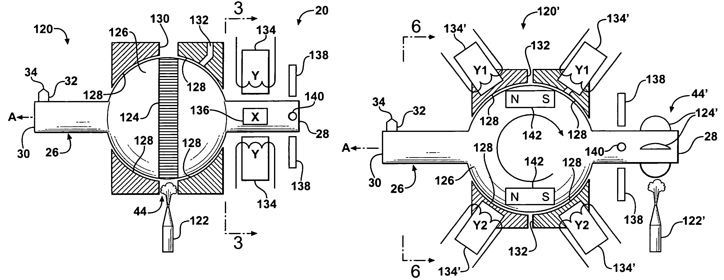
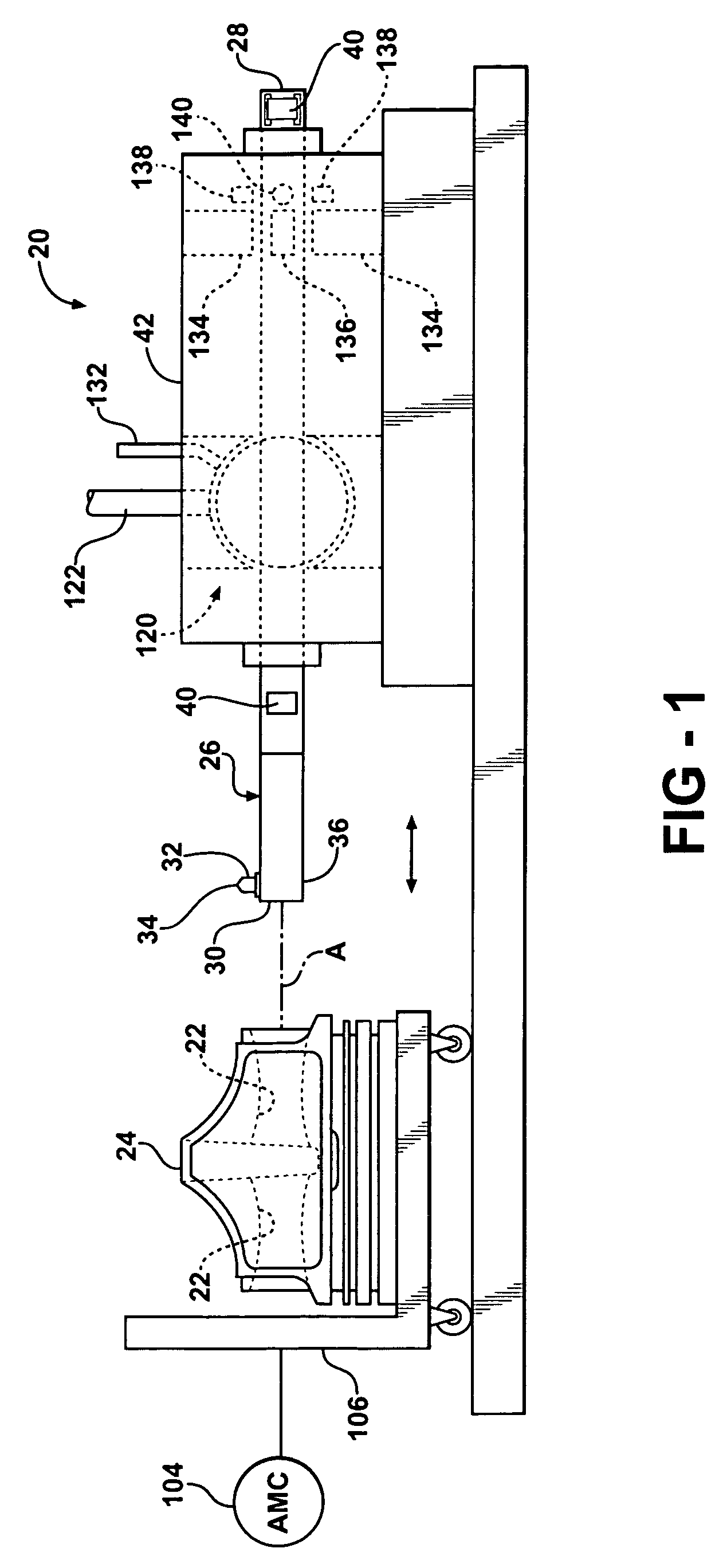
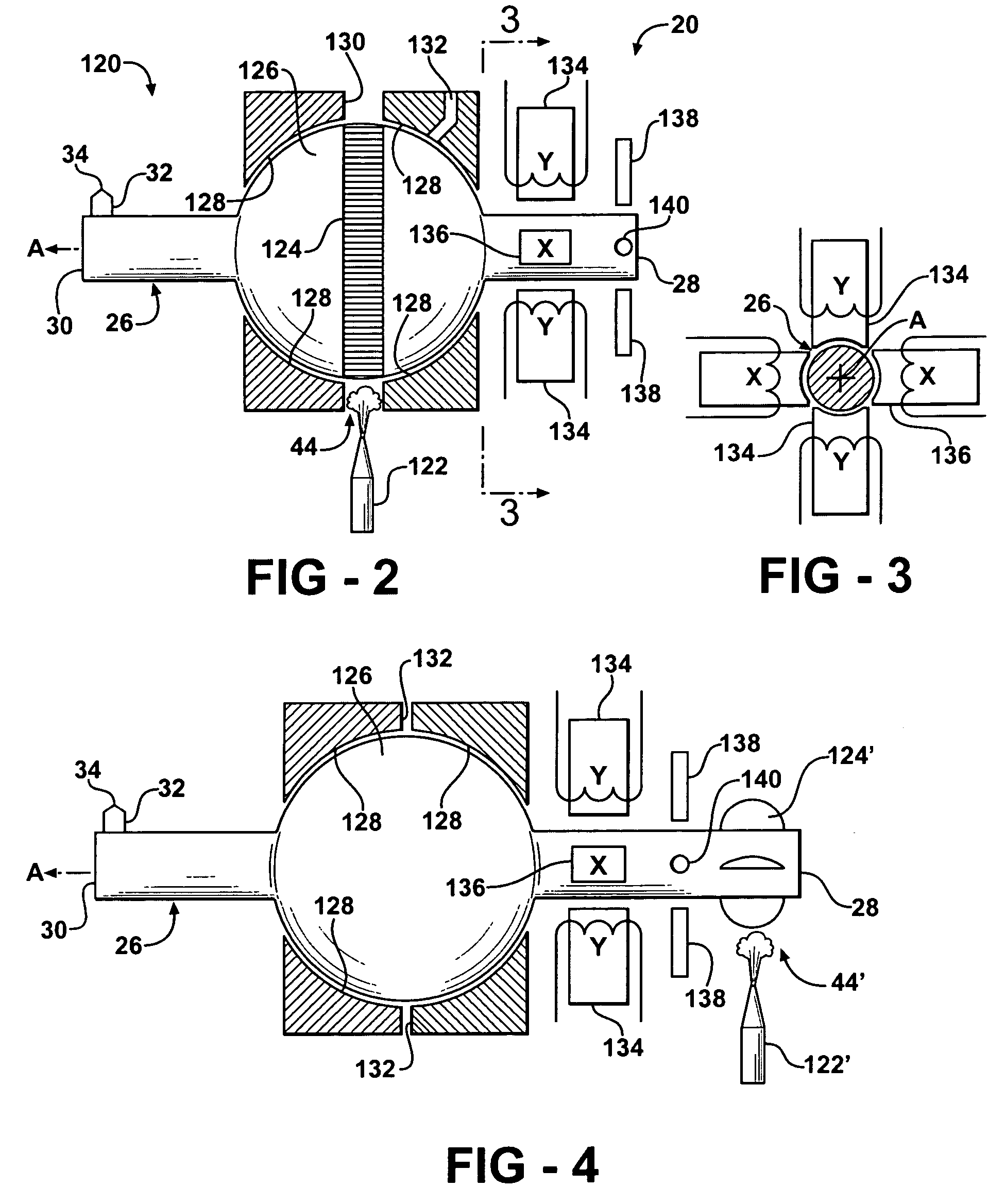
[0026]Referring to the Figures, wherein like numbers indicate like or corresponding parts throughout the several views, a high-speed spindle assembly is generally shown at 20 in FIGS. 1 and 2. The spindle assembly 20 is of the type for forming non-circular holes 22 in a work piece 24. In FIG. 1, the work piece 24 is shown for purposes of example only comprising a piston for an internal combustion engine. The non-circular hole 22 is illustrated as the pin hole for containing the so-called wrist pin (not shown). The work piece 24, however, may comprise any component and is not limited to pistons, engines or even automotive applications. Rather, any field of endeavor in which a non-circular hole 22 of high precision tolerance may benefit from the subject invention.

[0027]The assembly 20 includes a rigid shaft-like spindle, generally indicated at 26, extending along an long axis A between a rear end 28 and a shaping end 30. A shaping tool 32 extends radially outwardly from the spindle 26...


PUM

PropertyMeasurementUnit
angleaaaaaaaaaa
gravityaaaaaaaaaa
speedaaaaaaaaaa

Abstract

A machine tool assembly includes a high speed rotating spindle for forming extremely precise surface contours on a work piece. The spindle is supported on a spherical air bearing about its center of gravity. The spindle can be rotated through an air turbine drive system incorporated into the spherical air bearing to eliminate any undesirable moments about an axis perpendicular to the long spindle axis. The spindle is adjustable in pitch and yaw directions through the influence of X-Y actuators. The X-Y actuation system is preferably electromagnetic and provides a non-contact method of displacing the spindle shaft in a controlled manner at any speed.

Description

CROSS-REFERENCE TO RELATED APPLICATIONS[0001]This application claims priority to U.S. Provisional Application Ser. No. 60 / 666,674 filed Mar. 30, 2005.BACKGROUND OF THE INVENTION[0002]1. Technical Field[0003]This invention relates generally to high-speed spindle assemblies for shaping a non-circular hole in a work piece.[0004]2. Related Art[0005]Some production applications require the formation of non-circular holes. For example, in the manufacture of pistons for an internal combustion engine, the so-called pin holes formed for the wrist, or gudgeon, pin often have a slight trumpet shape opening toward the center for accommodating flex in the wrist pin. Additionally, this trumpet shape of the pin hole is optimally designed with a slight ovality to further account for distortion in the wrist pin as the piston moves through its various cycles. This trumpet shape and non-circular cross section of the pin hole must be formed to exacting tolerances. For example, tolerances in the range o...

Claims


Application Information

Patent Timeline
Patent Type & Authority Patents(United States)
IPC IPC(8): B23B3/00H02K7/09
CPCB23B41/04B23Q1/545B23Q1/70F16C41/00F16C32/0614F16C32/067F16C32/0696Y10T82/2583B23B2270/027B23B2270/38Y10T409/307616Y10T409/304424Y10T82/122Y10T82/10Y10T82/128B23B2215/245F16C2322/39B23B3/00
Inventor NICHOLL, ROBERT JOHNSCHMENK, MYRON JEFFERY
Owner FEDERAL MOGUL WORLD WIDE LLC
Why Eureka
Try Eureka