Manufacturing method of aerator impeller and integral injection molding impeller

A manufacturing method and integral injection molding technology, applied in chemical instruments and methods, water aeration, sustainable biological treatment, etc., can solve the problems of no disclosure of the mold structure, no disclosure of the mold release mechanism, affecting the efficiency of oxygen enhancement, etc. Good consistency, high production efficiency, and the effect of improving oxygenation efficiency

Inactive Publication Date: 2013-08-21
吴为国
View PDF1 Cites 5 Cited by
  • Summary
  • Abstract
  • Description
  • Claims
  • Application Information

AI Technical Summary

Problems solved by technology

The impeller of the impeller type aerator has metal welded impeller and plastic impeller. Most of the plastic impellers are assembled. Some people also propose integral injection molding impellers such as patent number: 02227273.9. There are many vertical ribs, the ribs block water during work, which affects the efficiency of oxygenation, and the patent does not disclose the mold structure, and the patent specification and drawings do not disclose the demoulding mechanism, so it cannot be implemented

Method used


Image

  • Manufacturing method of aerator impeller and integral injection molding impeller
  • Manufacturing method of aerator impeller and integral injection molding impeller
  • Manufacturing method of aerator impeller and integral injection molding impeller

Examples


Embodiment Construction

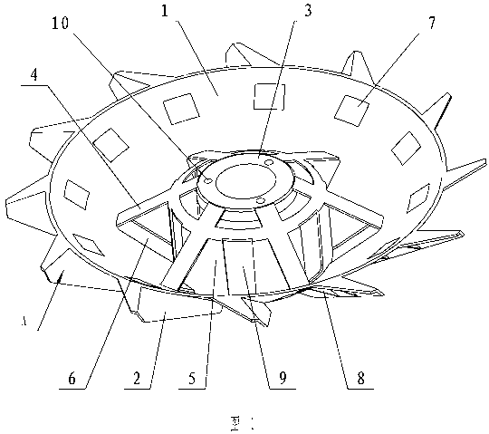
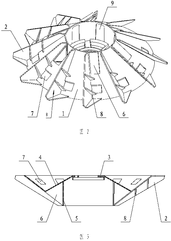
[0021] The present invention will be further described below with specific embodiment, see Figure 1-6 :

[0022] An injection molded impeller of an aerator is mainly composed of: a cone 1, a blade 2, a fixed plate 3, an upper support plate 4, a lower support plate 5, etc. The fixed plate 3 is formed with a connecting hole 10, and the connecting hole 10 can be fixed by bolts On the rotating shaft of the aerator, the fixed plate 3 is connected to the cone body 1 through the upper support plate 4 and the lower support plate 5, and the outer cone surface of the cone body 1 is connected with a plurality of blades 2, and the back side B of the blade has reinforcing ribs 8 to support the blade , be shaped on window 7 in the space of rib 8. There is a window 6 below the upper support plate 4, and the window 6 is designed for the mold structure. Its unexpected effect is to make the water in the cone 1 flow outward through the window, increase the water exchange capacity, and improve ...


PUM


Abstract

The invention relates a manufacturing method of an aerator impeller, and further relates to an integral injection molding impeller. According to the method, a die comprises a moving die and a fixed die, wherein the moving die comprises a main core and a plurality of auxiliary cores, the auxiliary cores enter the fixed die, and the lateral sides of the auxiliary cores fit into the fixed die and become upper supporting plates and windows. The main core is arranged in the middle of the die. A cavity of each impeller comprises a moving block and a stable block, wherein the moving block is connected with an angle erecting rod, a workpiece and the angle erector rod are pushed out together by a demolding mechanism conducting demolding, the angle erector rod ensures that the moving block slides out in an inclined mode, and the workpiece is erected out in a straight direction under the guiding action of the auxiliary cores and is separated from the moving block. The integral injection molding impeller mainly comprises a cone-shaped body, impellers, a fixing plate, an upper supporting plate and a lower supporting plate, wherein connecting holes are formed in the fixing plate, the fixing plate is connected with the cone-shaped body through the upper supporting plate and the lower supporting plate, the impellers are connected on the outer cone surface of the cone-shaped body, the back B of each impeller is provided with a reinforcing rib supporting the impeller, and a window is formed in the space of each reinforcing rib.

Description

technical field [0001] The invention relates to an aerator, in particular to a method for manufacturing the impeller of the aerator and the impeller, belonging to fish farming machinery. Background technique [0002] The aerator is a life-saving and stimulating equipment for fish and shrimp in aquaculture. Existing mechanical aerators mainly include three types: water wheel type, impeller type and water spray type, among which the impeller type aerator is the most widely used. The impeller of the impeller type aerator has metal welded impeller and plastic impeller. Most of the plastic impellers are assembled. Some people also propose integral injection molding impellers such as patent number: 02227273.9. There are many upright ribs, the ribs block water during work, which affects the efficiency of oxygenation, and the patent does not disclose the mold structure, and the specification and drawings of the patent do not disclose the demoulding mechanism, so it cannot be implem...

Claims


Application Information

Patent Timeline
Patent Type & Authority Applications(China)
IPC IPC(8): A01K63/04C02F7/00
CPCY02W10/10
Inventor 吴为国
Owner 吴为国
Why Eureka
Try Eureka