
Power tool

A power tool and movement technology, which is applied in the field of gun drill power tools, can solve the problems of unusable power tools and achieve the effects of quick replacement, accurate and reliable process, and improved work efficiency

Active Publication Date: 2013-08-21
POSITEC POWER TOOLS (SUZHOU) CO LTD
View PDF6 Cites 8 Cited by
  • Summary
  • Abstract
  • Description
  • Claims
  • Application Information

AI Technical Summary

Problems solved by technology

However, the device for automatically switching the cutter head will also drive the multi-cutter head wheel to move excessively, thus making the electric tool unusable

Method used


Image

  • Power tool
  • Power tool
  • Power tool

Examples


Embodiment Construction

[0069] In a preferred embodiment of the power tool of the present invention, the power tool is a power screwdriver, which can be divided into a pneumatic screwdriver, a hydraulic screwdriver and an electric screwdriver according to the power source, and there are also DC and AC in the electric screwdriver. Take a moving screwdriver as an example for specific description.

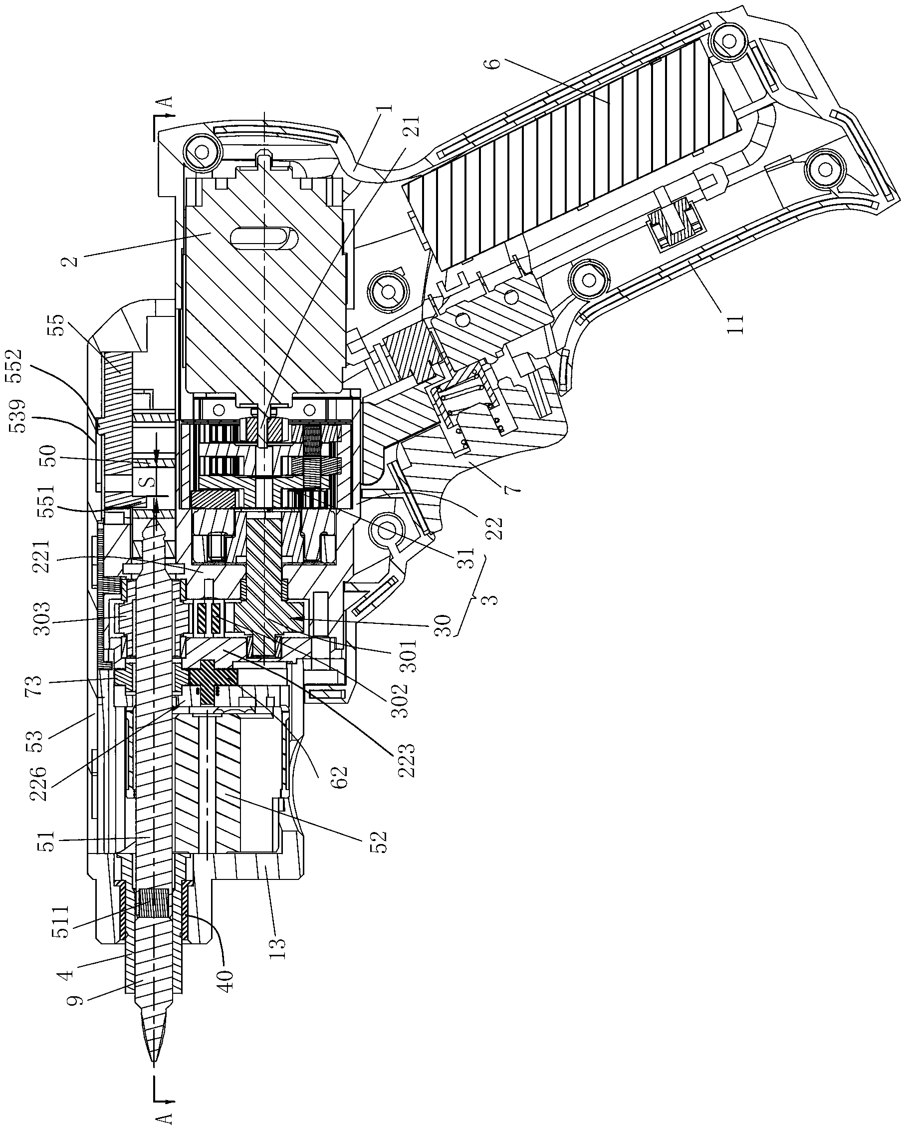
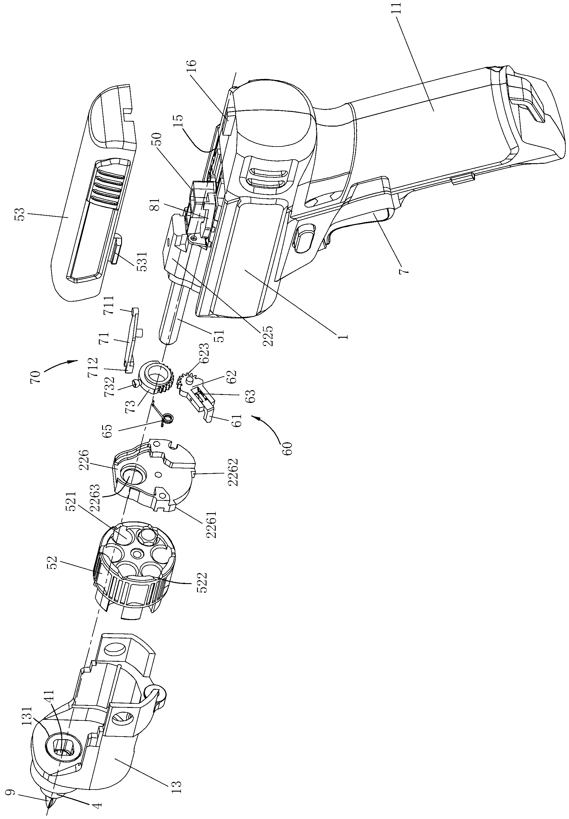
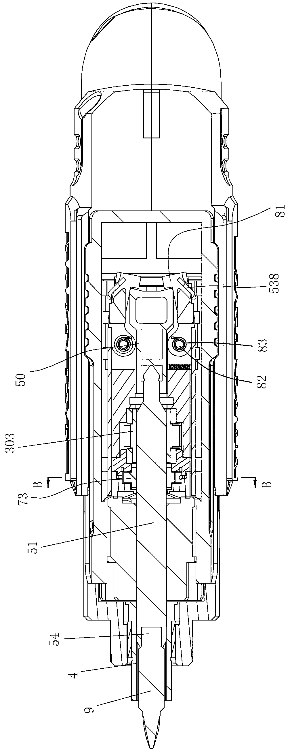
[0070] refer to Figure 1 to Figure 3 As shown, the DC electric screwdriver includes a casing 1 , a motor 2 , a battery 6 , a transmission mechanism 3 , a connecting shaft 51 , a storage clip 52 and an output shaft 4 . The casing 1 is composed of two symmetrical half shells assembled by screws (not shown). It has a horizontal part and a handle 11 part which is set at an obtuse angle with the horizontal part. The preferred angle of the present invention is 100 degrees to 130 degrees. Between degrees, it will be more comfortable when holding the handle 11 for operation. A button switch 7 is arranged on the t...


PUM


Abstract

The invention relates to a power tool comprising a housing, an output shaft, a storage clamp, a connecting shaft, an operation part and an automatic switching device. A motor and a transmission mechanism are arranged in the housing. The output shaft is provided with an axially arranged shelter hole sheltering an operating head. Rotating power output by the motor is transmitted to the output shaft through the transmission mechanism. The storage clamp comprises a plurality of sheltering bins for sheltering the operating head. The connecting shaft can penetrate through one of the sheltering bins to enable the operating head in the sheltering bin to axially move between an operating position fittingly connected with the output shaft and release position of the operating head dropping out of the sheltering bins. The operation part is arranged on the housing and used for controlling axial motion of the connecting shaft. The automatic switching device responds to motion of the operation part and adjusts the position of the storage clamp through a control mechanism, and the control mechanism can be meshed with or separated from the storage clamp and can be operated to move from the starting position to the finish position so as to drive the storage clamp. A stopping mechanism is arranged in the housing, and limits the control mechanism to be separated from the storage clamp when the control mechanism moves to the finish position.

Description

technical field [0001] The invention relates to a power tool, in particular to a gun drill type power tool which can realize the storage and quick replacement of working heads. Background technique [0002] Existing gun drill power tools generally include electric drills, electric screwdrivers and impact drills. [0003] An electric screwdriver is a commonly used electric tool for tightening screws to workpieces. When screws with different specifications need to be tightened during use, different working heads, that is, batch heads, should be replaced according to different screw specifications, that is, the originally installed working head should be removed, and then a working head with another structure should be installed. . In the occasions where the working head needs to be replaced frequently, it brings great inconvenience to the operator. On the one hand, it is cumbersome to replace the working head, and on the other hand, the removed working head is easily lost wh...

Claims


Application Information

Patent Timeline
Patent Type & Authority Applications(China)
IPC IPC(8): B25F3/00B25F5/00
Inventor 张伟王卿琳
Owner POSITEC POWER TOOLS (SUZHOU) CO LTD
Learn More