Hidden metal handle

A hidden, handle technology, applied in the direction of wing fan handles, furniture accessories, door/window accessories, etc., can solve the problems of occupying space and hidden dangers, and achieve the effect of saving space and eliminating hidden dangers.

Inactive Publication Date: 2013-08-21
常熟市联合金属制品有限责任公司
View PDF5 Cites 9 Cited by
  • Summary
  • Abstract
  • Description
  • Claims
  • Application Information

AI Technical Summary

Problems solved by technology

However, the current handle installation generally protrudes from the installation o

Method used


Image

  • Hidden metal handle

Examples


Example Embodiment

[0009] The present invention will be further described below in conjunction with specific embodiments.
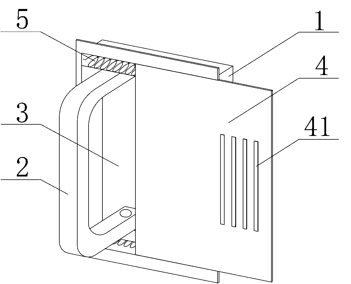
[0010] Such as figure 1 As mentioned, the hidden handle according to the present invention includes a base 1 and a handle 2 mounted on the base 1. A cavity 3 is provided on the base 1. The handle 2 can be rotated around the mounting end and stored in the cavity 3. The cavity 3 is provided with a sliding cover 4, and the sliding sliding cover 4 can open or close the cavity 3. When not in use, open the sliding cover 4, rotate the handle 2, store the handle 2 in the cavity 3, and then close the sliding cover 4. At this time, because the handle 2 is stored, the base and the installation are on the same plane, which saves space and eliminates potential safety hazards. When the handle 2 is to be used, cut open the slide cover 4, rotate the handle 2 to reset, and then close the slide cover 4. At this time, the handle 2 can function as a handle.

[0011] In the embodiment of the p...


PUM


Abstract

The invention discloses a hidden metal handle. The hidden metal handle comprises a base and a handle body installed on the base, wherein a cavity is formed in the base, the handle body can be rotated around the installation end to be stored in the cavity, a sliding cover is arranged on the cavity, and the cavity can be opened or closed by sliding of the sliding cover. The hidden metal handle has the advantages that due to the fact that the handle body can be stored in the cavity formed in the base when not used, space is saved and potential safety hazards are eliminated.

Description

technical field [0001] The invention relates to a metal handle, in particular to a metal handle which can be hidden. Background technique [0002] A handle is a component commonly installed on doors, cabinets, drawers, etc. With the continuous development of the economy and the continuous improvement of people's living standards, there are more and more styles and patterns of handles. In addition to realizing its use function, it has become a kind of decoration for people's home life. However, the current handle installation generally protrudes from the installation object, which not only takes up a certain space but also easily causes safety hazards. Contents of the invention [0003] Purpose of the invention: The purpose of the invention is to provide a hidden metal handle, which can be stored in the installation base when not in use, saving space and eliminating potential safety hazards. [0004] Technical solution: A concealed metal handle according to the present in...

Claims


Application Information

Patent Timeline
IPC IPC(8): E05B5/02A47B95/02
Inventor 顾佩荣
Owner 常熟市联合金属制品有限责任公司
Why Eureka
Try Eureka