Dehumidifier

一种除湿机、除湿部的技术,应用在制冷机、家用干衣机、机器的运行方式等方向,能够解决耗电量多、温度差变大等问题,达到热效率提高的效果

Active Publication Date: 2013-08-21
TAKUBO SEIKI SEISAKUSHO
View PDF5 Cites 3 Cited by
  • Summary
  • Abstract
  • Description
  • Claims
  • Application Information

AI Technical Summary

Problems solved by technology

[0003] However, in the case of conventional dehumidifiers, since the temperature difference between the humid air sucked from the outside and the cooled and dehumidified dry air increases, the power consumption required for cooling during dehumidification and temperature rise after dehumidification varies. many questions

Method used


Image

  • Dehumidifier
  • Dehumidifier
  • Dehumidifier

Examples


Embodiment Construction

[0029] Below, while referring to the attached Figure 1 Embodiments of the present invention will be described.

[0030] First, in figure 1 In the following, the structure of the dehumidifier according to the embodiment of the present invention will be described.

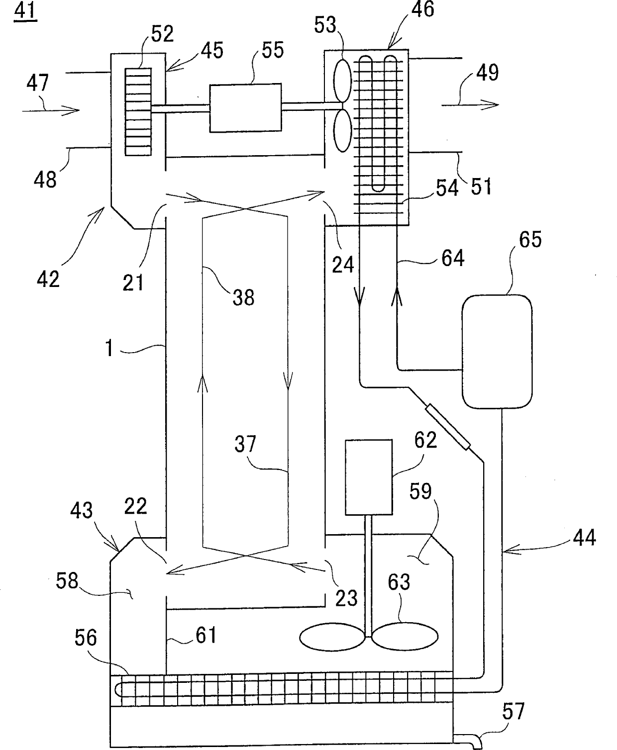
[0031] The dehumidifier 41 mainly consists of an air suction and discharge part 42, a heat exchanger 1, a dehumidification part 43, and a refrigerant circulation system 44. The above-mentioned air suction and discharge part 42 is arranged on one end of the above-mentioned heat exchanger 1, and the above-mentioned dehumidification part 43 is located On the other end of the above-mentioned heat exchanger 1 .

[0032]The air suction and discharge unit 42 is composed of a suction unit 45 and a discharge unit 46 . The suction part 45 has a suction port 48 through which the humid air 47 is sucked in, and a high-temperature fluid inlet 21 through which the humid air 47 flows into the heat exchanger 1 . The discharge un...


PUM


Abstract

A dehumidifier comprises a suction unit 45 which humid air 47 is sucked in, a dehumidifying unit 43 having a chiller 56 and for cooling down the humid air sucked in and for dehumidifying by condensing the moisture in the humid air, a discharge unit 46 having a heat radiator 54 and for heating and discharging dry air 49 as dehumidified at the dehumidifying unit, a refrigerant circulating system 44 for cooling down the humid air at the dehumidifying unit and for heating the dry air at the discharge unit, and a heat exchanger 1 for performing heat exchange between the humid air and the dry air as dehumidified at the dehumidifying unit.

Description

technical field [0001] The present invention relates to a dehumidifier installed in a room such as a drying room to dehumidify room air. Background technique [0002] Conventional dehumidifiers humidify the air by vaporizing the liquid refrigerant, cooling the cooler with the heat of vaporization, cooling the humid air drawn from the outside by the cooler, and condensing moisture in the humid air by cooling. Dehumidification, the compressor liquefies the refrigerant, heats the dehumidified dry air with the condensation heat generated during the liquefaction, and then discharges the dry air to the outside. [0003] However, in the case of conventional dehumidifiers, since the temperature difference between the humid air sucked from the outside and the cooled and dehumidified dry air increases, the power consumption required for cooling during dehumidification and temperature rise after dehumidification varies. many questions. [0004] In addition, Japanese Patent Applicatio...

Claims


Application Information

Patent Timeline
Patent Type & Authority Applications(China)
IPC IPC(8): F24F1/00F24F13/30
CPCB01D53/265B01D2259/4508D06F58/206D06F58/24F24F3/1405F24F3/153F24F12/006F24F13/30F24F2003/1446F24F2003/1452F28D9/0025F28D2021/0038F28F2230/00F28F2275/20Y02B30/56F25B29/00
Inventor 田洼定雄
Owner TAKUBO SEIKI SEISAKUSHO
Why Eureka
Try Eureka