Power transformer overheating fusing protective device

A technology for power transformers and protection devices, applied in the direction of emergency protection circuit devices, electrical components, electrical component structure associations, etc., can solve problems such as burnt coils, high overcurrent insurance setting, and shortened life, and achieve the effect of avoiding burning

Active Publication Date: 2013-08-21
PETROCHINA CO LTD +1
View PDF4 Cites 4 Cited by
  • Summary
  • Abstract
  • Description
  • Claims
  • Application Information

AI Technical Summary

Problems solved by technology

[0002] The power transformers are all set with rated capacity, and overcurrent protection is done through the current limiting insurance device installed on the periphery. However, due to human factors, the overcurrent insurance setting may be too high. Once the output current of the transformer is too large, the transformer will be overloaded. , the working current of the transformer exceeds the rated current, the load loss of the winding coil increases sharply, the coil heats up and causes the temperature of the transformer oil to rise, and the coil temperature reaches a critical value, the coil insulation varnish will age and deteriorate, and the insulation resistance will decrease, resulting in flashover short circuit and burning Coil; In addition, long-term operation of the transformer at a high temperature above 75°C will also lead to a decrease in the insulation of the coil and a shortened life. Temperature monitoring and automatic cut-off of equipment are used to protect the transformer, but the cost is high and there are requirements for the installation environment
For a large number of small and medium-sized power transformers, most of them do not have the conditions to install automatic protection equipment, and the small and medium-sized power transformers are overloaded or the top oil temperature exceeds the allowable value, resulting in the burning of the coil windings.

Method used


Image

  • Power transformer overheating fusing protective device
  • Power transformer overheating fusing protective device
  • Power transformer overheating fusing protective device

Examples


Embodiment Construction

[0015] Below in conjunction with accompanying drawing, the present invention will be further described:

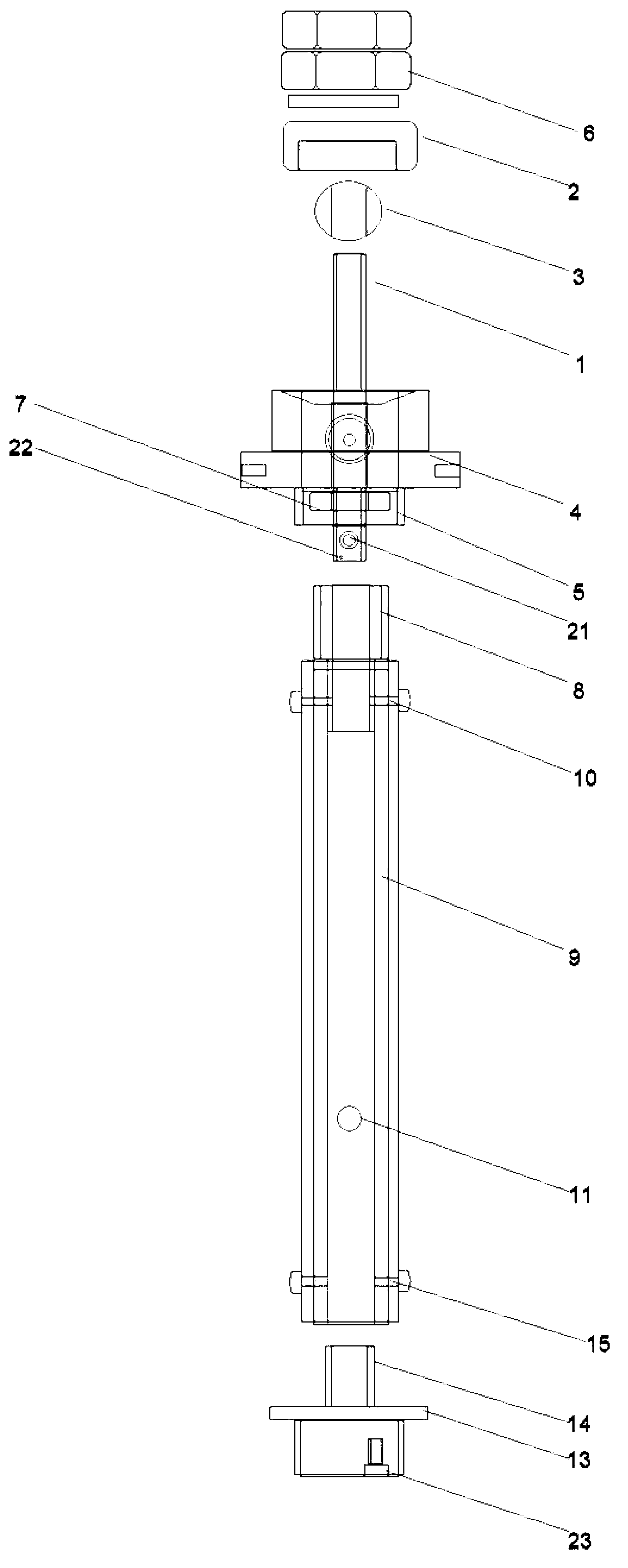
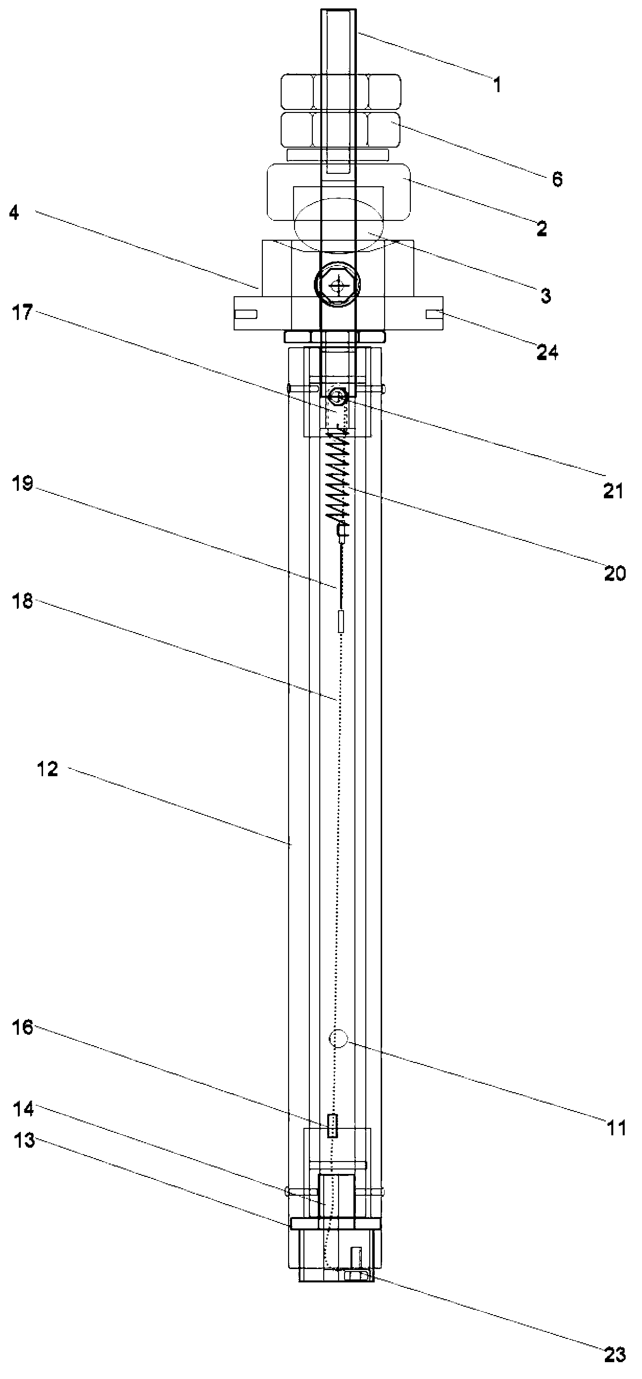
[0016] Power transformer overheating fuse protection device, including conductive rod 1, insulating tube 9 and wiring sleeve 29;

[0017] combine figure 1 : The conductive rod 1 is sequentially covered with a ceramic gland 2, a sealing rubber ball 3, a sleeve gland 4 and a fixed sleeve 5 from top to bottom, and the compression nut group 6 at the upper end of the ceramic gland 2 and the conductive rod 1 Screw connection and the screw connection of the fixed sleeve 5 and the locking fixing nut 7 to fasten each device on the conductive rod 1, the fixed sleeve 5 is screwed to the threaded side of the pup joint 8 through the internal thread provided at the lower end , the unthreaded side of the puppet 8 is inserted into the upper end of the insulating tube 9, and connected by rivets through the puppet connection hole 10 opened on the upper end of the insulating tube 9, the mid...


PUM


Abstract

The invention discloses a power transformer overheating fusing protective device which can solve the problem that a coil winding is burnt caused by the situation that a small-and-medium sized power transformer is overloaded or top oil temperature exceeds a permissible value. The power transformer overheating fusing protective device is internally installed in a high voltage side wiring bushing of a transformer, and is connected with the high voltage side input end of the transformer in series, and a ring seat on the bottom of the wiring bushing is inserted below an upper cover of the transformer, is dipped into conduction oil of the transformer, and directly senses oil temperature changes. When load of the transformer is oversized or the temperature is high to reach a critical value, an overcurrent insurance fuse wire section or a melt crimping pipe in the device is fused, and power supply of a coil of the transformer is cut. The coil of the transformer is prevented from being burnt, and the transformer is protected.

Description

technical field [0001] The invention belongs to the field of power transformation and distribution equipment, in particular to an overheating fusing protection device for a power transformer. Background technique [0002] The power transformers are all set with rated capacity, and overcurrent protection is done through the current limiting insurance device installed on the periphery. However, due to human factors, the overcurrent insurance setting may be too high. Once the output current of the transformer is too large, the transformer will be overloaded. , the working current of the transformer exceeds the rated current, the load loss of the winding coil increases sharply, the coil heats up and causes the temperature of the transformer oil to rise, and the coil temperature reaches a critical value, the coil insulation varnish will age and deteriorate, and the insulation resistance will decrease, resulting in flashover short circuit and burning Coil; In addition, long-term o...

Claims


Application Information

Patent Timeline
Patent Type & Authority Applications(China)
IPC IPC(8): H02H7/04H01F27/40
Inventor 汤凯米忠庆梁玉波李鹤王洪亮
Owner PETROCHINA CO LTD
Why Eureka
Try Eureka