Real-time monitoring device and monitoring method for relay protection equipment

A relay protection and real-time monitoring technology, applied in the direction of circuit devices, electrical components, etc., can solve problems such as neglect or misreading, malfunction or refusal of relay protection equipment, crash of relay protection equipment, etc., to improve safety performance , Avoid incorrect actions, avoid misjudgments and missed effects

Active Publication Date: 2016-05-04
STATE GRID CORP OF CHINA +3
View PDF5 Cites 0 Cited by
  • Summary
  • Abstract
  • Description
  • Claims
  • Application Information

AI Technical Summary

Problems solved by technology

[0002] In the daily operation of the power system, the relay protection equipment occasionally crashes. If the crash is not detected and dealt with in time, the relay protection equipment will malfunction or refuse to operate, resulting in serious electrical accidents
[0003] Usually, in the power system, inspectors are sent to visually observe the lighting status of the running lights on the relay protection equipment to judge its operation status, but human inspections are prone to neglect or misreading, and often fail to find out the breakdown of the relay protection equipment in time

Method used


Image

  • Real-time monitoring device and monitoring method for relay protection equipment
  • Real-time monitoring device and monitoring method for relay protection equipment

Examples


Embodiment 1

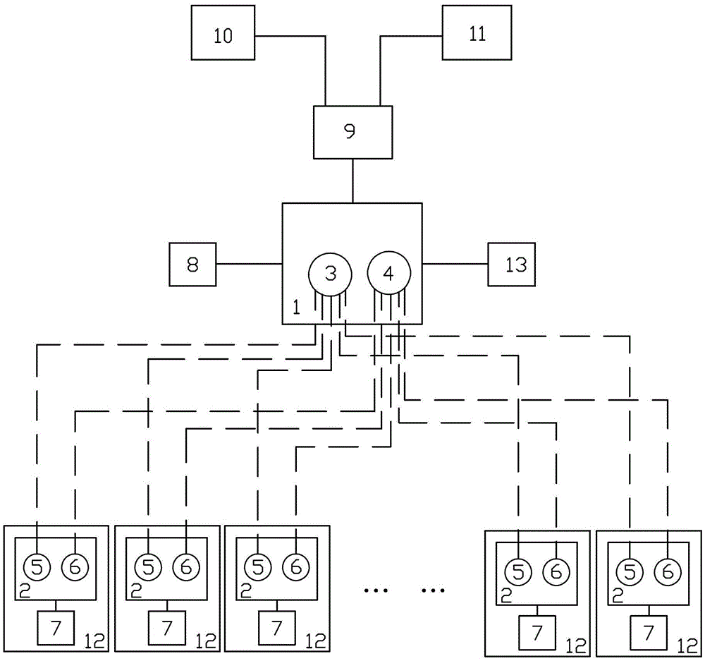
[0019] Embodiment 1: Several original relay protection devices 12 in the power system are connected to the master control device 9, the master control device 9 is connected to the background machine 10 and the monitoring center 11, and the master control device 9 is used to control the entire power system running. as attached figure 1 As shown, the newly added real-time monitoring device for relay protection equipment includes a first transceiver device 1 and a second transceiver device 2 , and an inspection device 7 capable of self-checking the relay protection device 12 . The first transceiver device 1 is connected with the master control device 9, and specifically includes a first sending module 3 and a first receiving module 4, and the second transceiver device 2 is arranged on a relay protection device 12, and specifically includes a second sending module 5 and a first receiving module 4. Two receiving module 6 . The first sending module 3 and the second receiving modul...


PUM


Abstract

The invention relates to a real-time monitoring device for relaying protection equipment. The real-time monitoring device for the relaying protection equipment comprises a first transmitter-receiver set, a second transmitter-receiver set and a checking device, wherein the first transmitter-receiver set is connected with a master control device and capable of transmitting and receiving signals, the second transmitter-receiver set is arranged on the relaying protection equipment and capable of transmitting signals with the first transmitter-receiver set, the checking device is arranged on the relaying protection equipment and checks the relaying protection equipment, and the second transmitter-receiver set is connected with the checking device through signals. The invention further relates to a method which adopts the relaying protection equipment real-time monitoring device to conduct real-time monitoring on the relaying protection equipment. According to the real-time monitoring device and the monitoring method for the relaying protection equipment, real-time monitoring for the relaying protection equipment can be achieved, so that all operation exception can be found in time, incorrect operation caused by long-time abnormal operation of the relaying protection equipment can be avoided, incorrect judgment and omission of device states caused by manual inspection tour are also avoided, and safety performance of an electrical power system is greatly improved.

Description

technical field [0001] The invention relates to a real-time monitoring device for relay protection equipment and a monitoring method thereof. Background technique [0002] In the daily operation of the power system, the relay protection equipment occasionally crashes. If the crash is not detected and dealt with in time, the relay protection equipment will malfunction or refuse to operate, resulting in serious electrical accidents. [0003] Usually, in the power system, inspectors are sent to visually observe the lighting status of the running lights on the relay protection equipment to judge its operation status, but human inspections are prone to neglect or misreading, and often fail to find out the breakdown of the relay protection equipment in time . Contents of the invention [0004] The object of the present invention is to provide a real-time monitoring device for relay protection equipment for monitoring the operation status of relay protection equipment in a power...

Claims


Application Information

Patent Timeline
Patent Type & Authority Patents(China)
IPC IPC(8): H02J13/00
Inventor 邬大为吴军侯睿龚海华
Owner STATE GRID CORP OF CHINA
Why Eureka
Try Eureka