
tools for machining workpieces

A technology of tools and components, which is applied in the field of tools for metal workpieces, can solve problems such as mechanical deformation of workpieces, and achieve the effects of cheap manufacturing, simple structure, and high efficiency

Active Publication Date: 2016-07-13
PMG ASTURIAS POWDER METAL
View PDF8 Cites 0 Cited by
  • Summary
  • Abstract
  • Description
  • Claims
  • Application Information

AI Technical Summary

Problems solved by technology

Due to the rotational movement of the rolling tool along the surface of the workpiece at a predefined number of tool revolutions, there is a risk of mechanical deformation of the workpiece

Method used


Image

  • tools for machining workpieces
  • tools for machining workpieces
  • tools for machining workpieces

Examples


Embodiment Construction

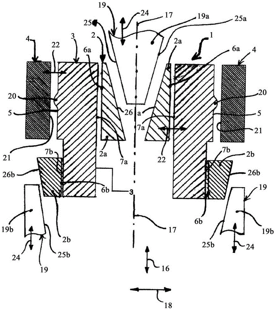
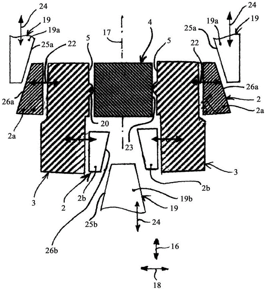
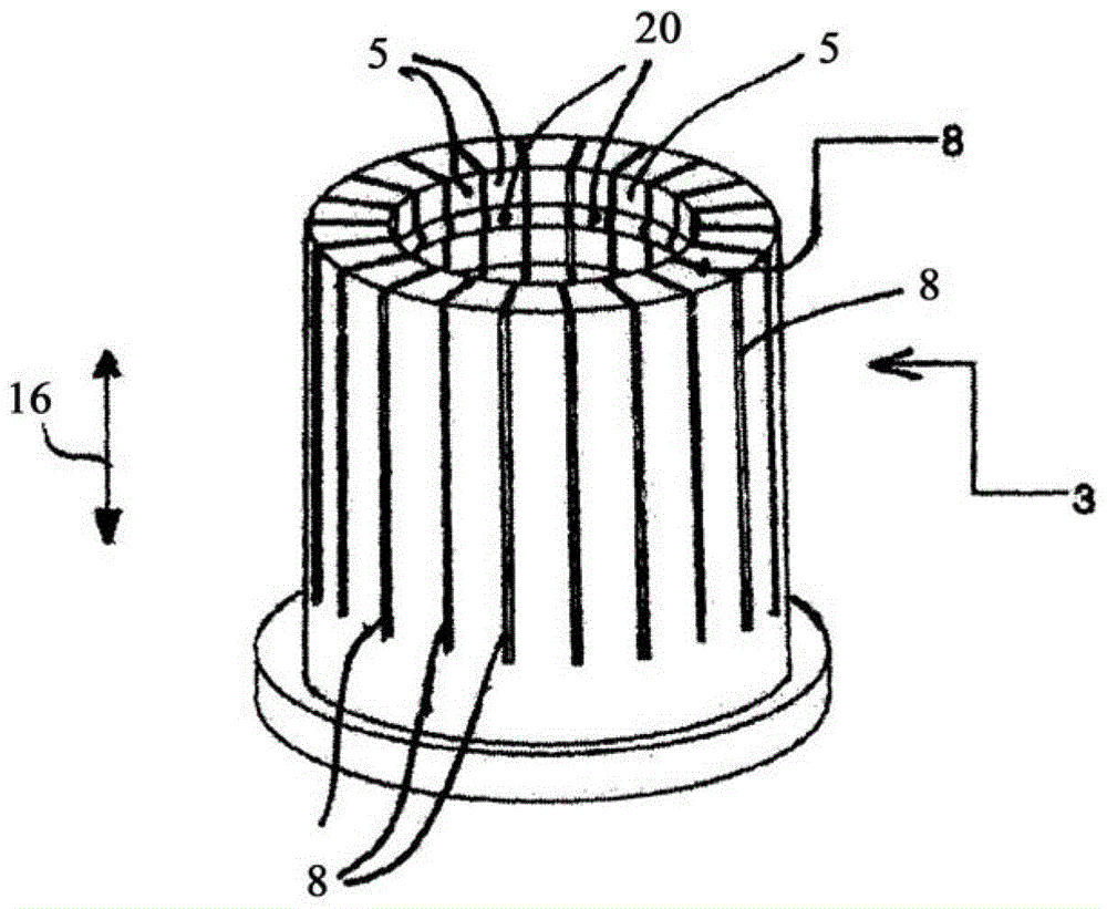
[0069] according to figure 1 , the tool 1 for forming has a transmission part 2 and a forming part 3 . The transmission part 2 comprises a first transmission part part 2a and a second transmission part part 2b. The two transmission element parts 2 a and 2 b are arranged at a distance from each other in the axial direction 16 of the tool 1 , ie along the central longitudinal axis 17 of the tool 1 . The radial extension of the profiled part 3 can vary in the radial direction 18 . For this purpose, the movement of individual or all transmission element parts 2 a , 2 b in radial direction 18 is controlled. by means of only figure 1 The movement control is carried out by corresponding drive members 19a, 19b schematically shown in .

[0070] The profiled part 3 has a contact surface 5 with a profiled relief 20 for a provided radially inner surface 21 of the annular workpiece 4 that is to be profiled in the working direction 22 . The working direction 22 runs substantially in th...


PUM


Abstract

The invention relates to a tool (1) for machining a workpiece (4). The tool (1) contains a tool element (3) that can be moved in the working direction (22) in order to be applied to a surface (21) of the workpiece (4). A drive element (19, 19a, 19b) that can be driven in a drive direction (24) transversally to the working direction (22) of the tool element (3) interacts with the tool element (3) to transmit a force. A transmission element (2, 2a, 2b) for transmitting force between the drive element (19, 19a, 19b) and the tool element (3) is positioned between the tool element (3) and the drive element (19, 19a, 19b).

Description

technical field [0001] The invention relates to a tool for machining workpieces, especially metal workpieces. Background technique [0002] A method for forming a backing on an internal toothing of a sliding sleeve produced by powder metallurgy for a shift transmission is known from document WO 2010 / 075600 A1. The recess in the tooth flank region of the inner toothing of the ring part is referred to here as backing. The forming is carried out by means of a rolling tool, wherein the backing is formed from the backing region by back-side rolling using the extrusion method of plastic material. Due to the rotational movement of the rolling tool along the surface of the workpiece at a predefined number of tool revolutions, there is a risk of mechanical deformation of the workpiece. [0003] A tool for compacting a sintered part or a powder for compacting a sintered part to be produced is known from document EP2060346A2. The tool has a compacting element whose radial dimension ...

Claims


Application Information

Patent Timeline
Patent Type & Authority Patents(China)
IPC IPC(8): B21J5/12B21K1/30B21J13/02
CPCB21J5/12B21J13/025B21K1/30
Inventor 迭戈·卡斯特罗·梅嫩德斯-卡斯塔涅多胡安·伊格纳西奥·洛佩斯·马丁内茨伊万·若泽·普雷萨·洛佩斯
Owner PMG ASTURIAS POWDER METAL
Learn More