Telescopic protective covering

A technology for a protective cover and a cover segment, which is applied in the field of protective covers, can solve the problems of high cost and cost-intensive manufacturing of protective covers, and achieve a simple method and the effect of supporting

Active Publication Date: 2013-08-21
ARNO ARNOLD
View PDF5 Cites 12 Cited by
  • Summary
  • Abstract
  • Description
  • Claims
  • Application Information

AI Technical Summary

Problems solved by technology

However, this makes such a protective cover complex and expensive to produce
In addition, the weight of the protective cover is significantly increased, so that the protective cover with a greater length can no longer move at the required speed due to its high weight

Method used


Image

  • Telescopic protective covering
  • Telescopic protective covering
  • Telescopic protective covering

Examples


Embodiment Construction

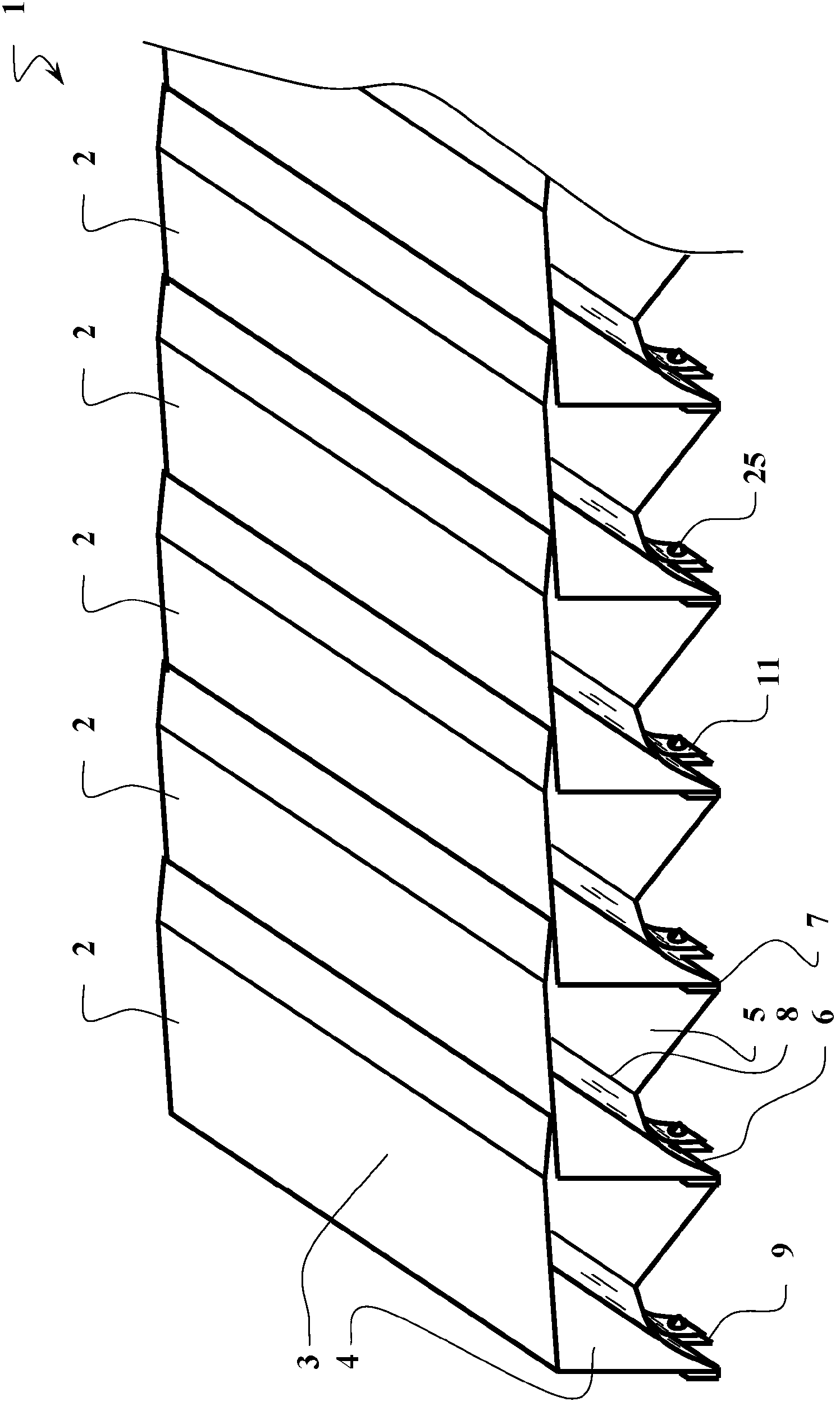
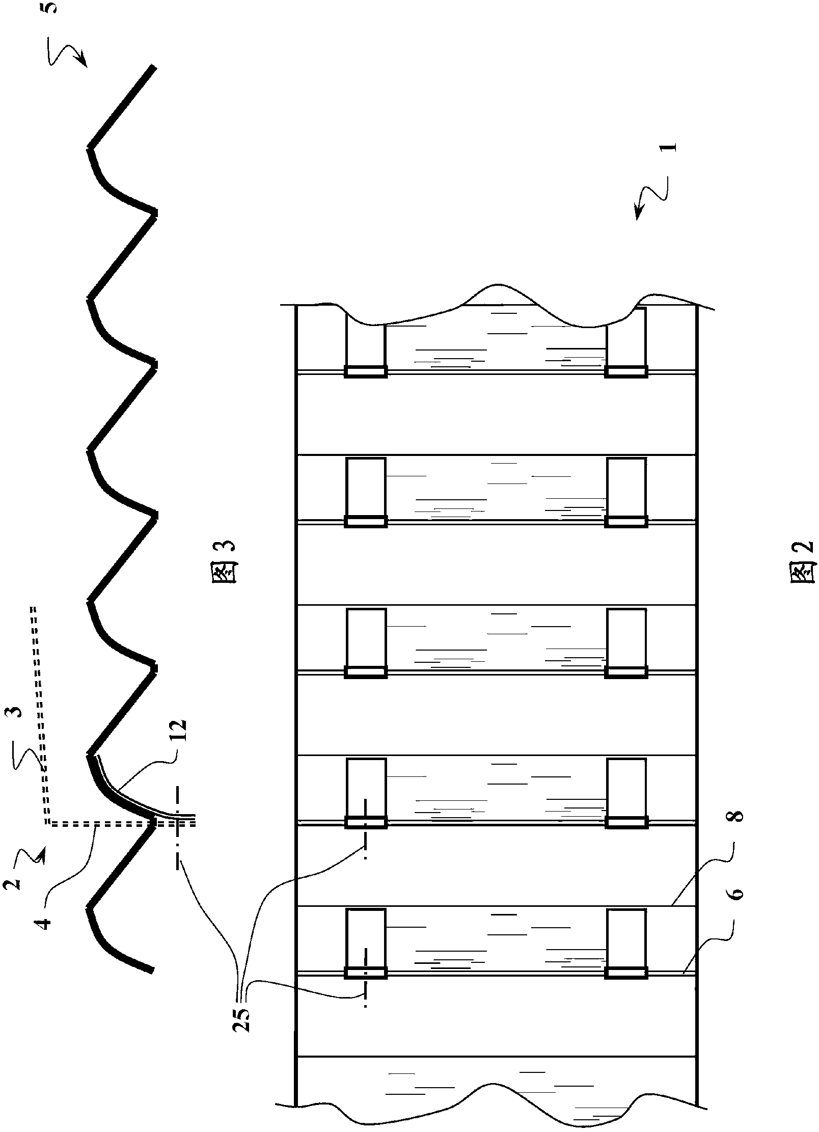
[0039] exist figure 1 The protective hood 1 shown in has a plurality of protective hood segments 2 , which are produced from sheet metal, for example stainless steel. The protective hood segments 2 are each substantially L-shaped and each have a covering leg 3 and a supporting leg 4 . In this case, the protective hood segments 2 are arranged relative to one another in such a way that they can be moved telescopically relative to one another, wherein the covering legs 3 of adjacent protective hood segments 2 correspondingly form an overall substantially closed surface. lean against each other.

[0040] In the illustrated embodiment, the boot segments 2 are connected via flexible connecting elements 5 in the form of rails made of an inherently rigid plastic material, in particular polypropylene (PP), so that in the event of a tensile load, The protective hood segments 2 move when the protective hood 1 is lengthened or shortened, wherein the connecting element 5 simultaneously s...


PUM


Abstract

The invention relates to a protective covering comprising a plurality of substantially L-shaped protective covering segments (2, 16) comprising a cover leg (3, 17) and a support leg (4, 18) which are arranged relative to one another in such a way that they can be displaced telescopically with respect to one another, wherein the cover legs (3, 17) of adjacent protective covering segments (2, 16) each come to bear on one another with the formation of an overall substantially closed surface, and comprising at least one band- or web-shaped flexible connecting element (5, 31) which interconnects the support legs (4, 18) of the protective covering segments (2, 16) so as at least to impart a tensile force. Disposed on each of the support legs (4, 18) is at least one elastic resetting element (11, 32) such that said element is fastened by its first end to the support leg (4, 18) and abuts with its second end with prestressing against a portion of the connecting element (5, 31) so as to urge said portion in the direction of the support leg (4, 18).

Description

technical field [0001] The invention relates to a protective cover according to the preamble of claim 1 . Background technique [0002] Protective covers of the mentioned type are used, for example, in machine tools to protect movable parts, such as drives, against inadvertent access by the user to the machine and to close off the working chamber of the machine tool so that no chips or other parts and The particles exit in a manner that is harmful to the user. For this purpose, typical protective hoods have protective hood segments in the form of L-shaped plates, which are telescopically joined to one another by means of one of their legs from behind and thus form a substantially closed hood. However, since in particular the overlapping legs overlap each other only loosely, an insufficiently tight closure can occur or constructively complex fillings must be carried out. Protective covers of this type are therefore usually additionally provided with a closing bellows on the...

Claims


Application Information

Patent Timeline
Patent Type & Authority Applications(China)
IPC IPC(8): B23Q11/08
CPCB23Q2011/0808B23Q11/0825B23Q11/0816
Inventor 沃尔夫-马蒂亚斯·曼格托马斯·克罗伊策
Owner ARNO ARNOLD
Why Eureka
Try Eureka