
Friction clutch

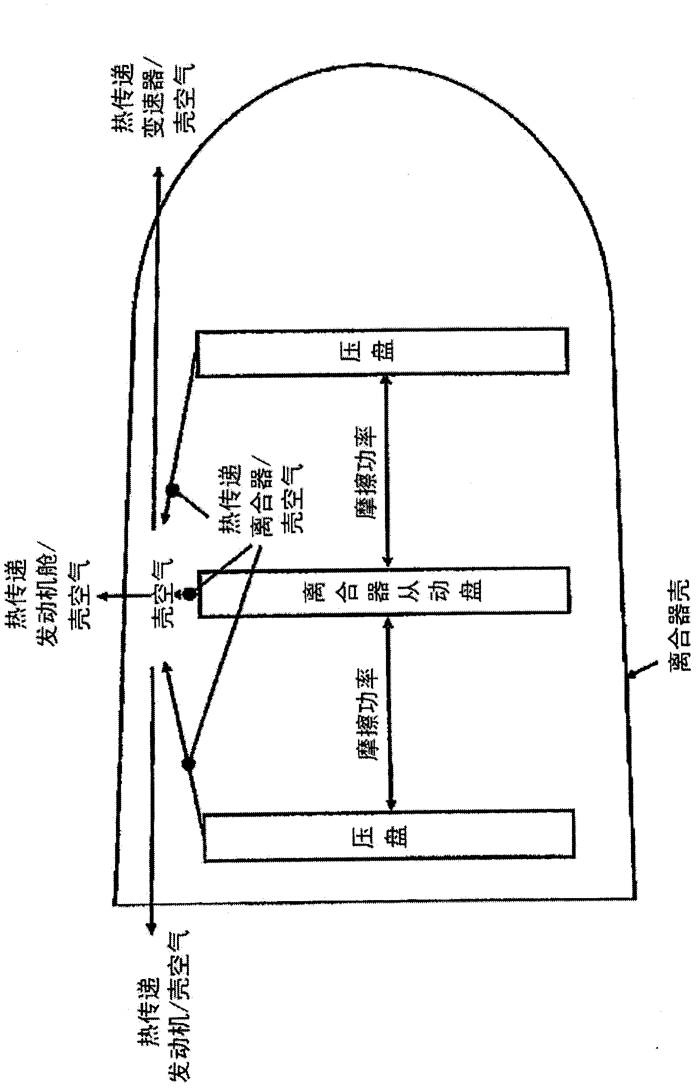
A technology of friction clutches and clutches, which is applied in the direction of friction clutches, clutches, mechanically driven clutches, etc., and can solve problems such as shortened service life, limited usability and usability, and reduced module accuracy

Inactive Publication Date: 2013-08-21
SCHAEFFLER TECH AG & CO KG
View PDF8 Cites 0 Cited by
  • Summary
  • Abstract
  • Description
  • Claims
  • Application Information

AI Technical Summary

Problems solved by technology

[0009] 1) Without active cooling, the usability of the clutch and thus the vehicle is thermally limited or the clutch is thermally overloaded, which shortens the service life;
[0010] 2) Using the temperature sensor on the outer wall of the shell, the value of the shell air temperature cannot be judged with sufficient precision, because the temperature measured on the outer wall of the shell is related to the volume of the shell casting, the heat flow in the engine compartment and the shell air
Due to the increased complexity, a considerable number of input signals are required which reduce the accuracy of the module, thereby limiting the car's drivability or serviceability, or causing the clutch to overheat or be damaged

Method used


Image

  • Friction clutch
  • Friction clutch

Examples


Embodiment Construction

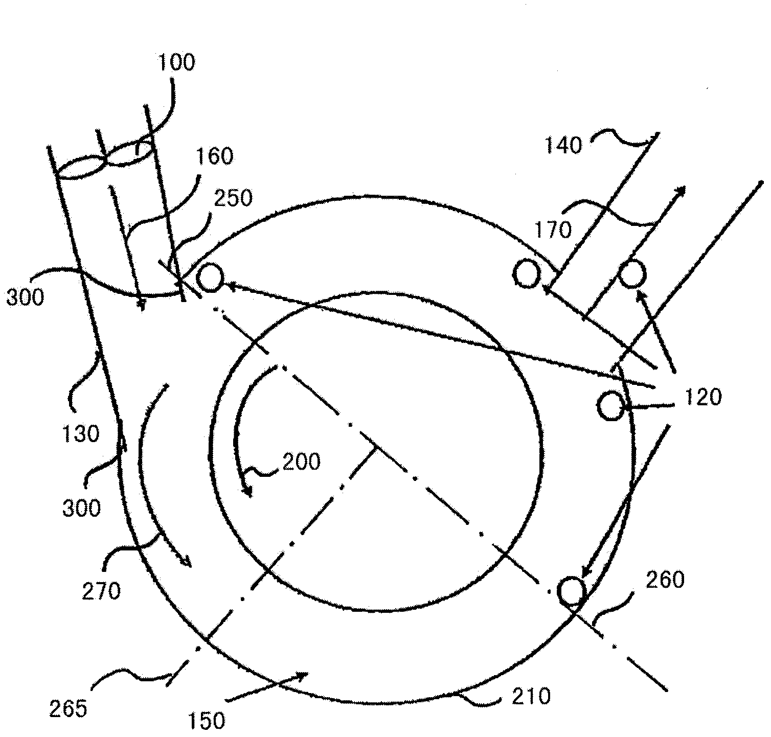
[0031] In order to determine the clutch temperature when active shell air cooling 100 is used, a temperature sensor 120 is arranged in shell air volume 150 . The reference numeral 120 designates not only the temperature sensor but also its position. figure 2 Some examples are given in . Particularly suitable sensor locations 120 can be determined from detection of the flow conditions within the clutch or clutch housing. Viewed from the intake channel 130 , in the flow direction 270 of the air conveyed through the intake channel 130 , favorable sensor positions 120 are the angular range between 90° (reference number 265 ) and 360° (reference number 250 ), especially 180° degrees (reference number 260 ) to 360 degrees (reference number 250 ), or the temperature sensor 120 is arranged in the air outlet channel 140 . An advantageous measuring position is therefore generally provided where the clutch housing interior air 150 has not yet been mixed with fresh air 160 , ie is not ...


PUM


Abstract

The invention relates to a friction clutch in a motor vehicle, comprising a clutch bell housing (210), at least one air inlet duct (130) arranged on the clutch bell housing for cooling the clutch bell housing, at least one air outlet duct (140) arranged on the clutch bell housing, and at least one temperature sensor (120). The invention further relates to a method for determining a clutch temperature of a friction clutch.

Description

technical field [0001] The invention relates to a friction clutch having the features of the preamble of claim 1 and a method according to the preamble of claim 7 , in particular to air cooling of the clutch housing. Background technique [0002] Friction clutches in automobiles usually have a clutch housing. In transmissions with dry friction clutches and active cooling, the housing air temperature in the clutch housing cannot be calculated with sufficient accuracy online (ie in the vehicle) using current clutch temperature models. Therefore, it is necessary to apply temperature sensors, thereby optimizing the clutch temperature model. [0003] A clutch temperature model provides signals used for clutch protection strategies. The clutch protection strategy protects the clutch from overheating and thus from effects that occur at higher temperatures, such as fading, thermal shock, etc. Due to the generated frictional power, the clutch disc, the clutch disc and other compon...

Claims


Application Information

Patent Timeline
Patent Type & Authority Applications(China)
IPC IPC(8): F16D13/72
CPCF16D13/72F16D48/06F16D2300/021F16D2300/26F16D2500/30404F16D2500/30405F16D2500/70446
Inventor L·G·麦克米利安D·雷德尔G·屈斯特勒尔
Owner SCHAEFFLER TECH AG & CO KG
Learn More