Determination of media characteristics during filling level measurement

A material level measurement and material level technology, which is applied in the field of medium characteristics determination, and can solve the problems of inaccurate material level measurement results.

Active Publication Date: 2013-08-21
VEGA GRIESHABER GMBH & CO
View PDF7 Cites 12 Cited by
  • Summary
  • Abstract
  • Description
  • Claims
  • Application Information

AI Technical Summary

Problems solved by technology

[0009] It was established here that level measurements based on radar level sensors are often inaccurate

Method used


Image

  • Determination of media characteristics during filling level measurement
  • Determination of media characteristics during filling level measurement
  • Determination of media characteristics during filling level measurement

Examples


Embodiment Construction

[0049]If the same reference signs are used in different figures in the following description of the figures, they indicate identical or similar elements. However, identical or similar elements can also be identified by different reference signs.

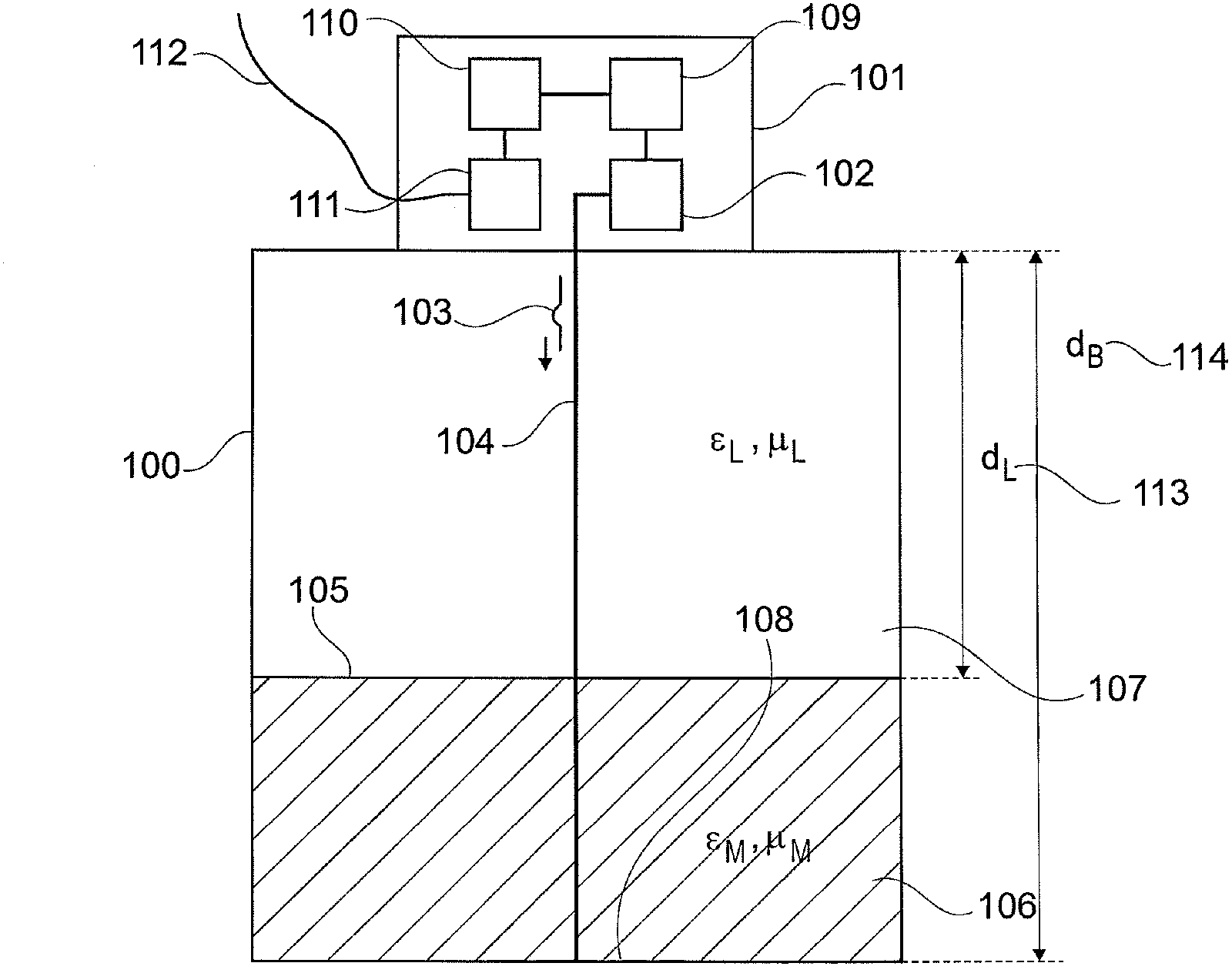
[0050] Common to all methods is that the signal used for the measurement is normally located in the area of ​​influence of another medium, which shall subsequently be referred to as superimposed medium, on its way from the filling level measuring device to the filling surface and / or interface layer surface.

[0051] A superimposed medium is a medium or a mixture of different media which is located between the point of emission of the measuring signal of a level measuring device (for example an antenna of a filling level measuring device) and the surface of the medium to be measured or between the surface of the medium to be measured. Between the point of emission of the measuring signal of a level measuring device (eg an antenna of a...


PUM


Abstract

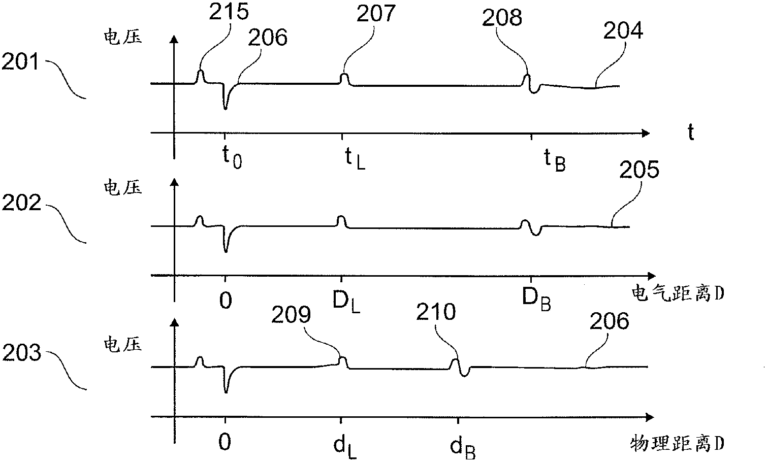
In order to calculate the filling level of a container, two echo curves are detected which represent the reflection behaviour along two different measuring sections. The corresponding measuring signals travel different electrical distances on their way to the surface of the filling level or the surface of an interfacial layer. A characteristic value, which reflects a physical characteristic of the covering medium, can be calculated from the two echo curves. The filling level can thus be determined with increased accuracy from said value.

Description

technical field [0001] The invention relates to the determination of the properties of the medium when measuring all kinds of filling levels. In particular, the invention relates to a fill level measuring device operating according to the transit time method, a fill level measuring device, a use for fill level measurement and a method. Background technique [0002] In level sensors operating according to the FMCW (Frequency Modulated Continuous Wave) or pulse-transit-time method, electromagnetic or acoustic waves are emitted in the direction of the filling surface. The sensor then registers the echo signals reflected by the filling, the container arrangement and the container itself, and deduces the corresponding fill level from this. [0003] For example, level sensors operating according to the time-of-flight method may belong to sensors which determine the distance to the filling surface using ultrasound, radar, guided radar, FMCW radar, pulse radar, CW (continuous wave)...

Claims


Application Information

Patent Timeline
Patent Type & Authority Applications(China)
IPC IPC(8): G01F23/296G01N29/024
CPCG01F23/2962
Inventor 罗兰·韦勒卡尔·格里斯鲍姆
Owner VEGA GRIESHABER GMBH & CO
Why Eureka
Try Eureka