
Antenna system for a level measurement apparatus

a level measurement and antenna system technology, applied in the direction of antennas, engine lubrication, liquid/fluent solid measurement, etc., can solve the problems of large constructional space, large system size, and difficulty in exact matching of waveguide dimensions to the transmission frequency range of microwave signals, so as to reduce the constructional length reduce the size of the antenna system, and reduce the effect of wave propagation angl

Inactive Publication Date: 2005-05-10
VEGA GRIESHABER GMBH & CO
View PDF12 Cites 40 Cited by
  • Summary
  • Abstract
  • Description
  • Claims
  • Application Information

AI Technical Summary

Benefits of technology

This configuration reduces the antenna system's longitudinal extension by up to 60%, enhances measurement accuracy, and allows for use in constrained spaces and high-frequency ranges, while providing explosion-proof isolation and cost-effective production.

Problems solved by technology

Horn antennas are already known from prior art in the field of the filling level measuring technology; however, all of them exhibit certain problems due to their constructional configuration and length.
This solution, however, is again based on the construction-inherent problem that such an antenna system requires a large constructional space—which is mainly extended in the longitudinal direction.
Hereby, the exact matching of the waveguide dimensions to the transmission frequency range of the microwave signal is problematic for allowing only the fundamental mode of wave to propagate within the waveguide.
Matching adjustments for the waveguide, which are not exact enough, can lead to signal distortions due to wave dispersion, eventually resulting in a misrepresented measurement result.

Method used


Image

  • Antenna system for a level measurement apparatus
  • Antenna system for a level measurement apparatus
  • Antenna system for a level measurement apparatus

Examples


Embodiment Construction

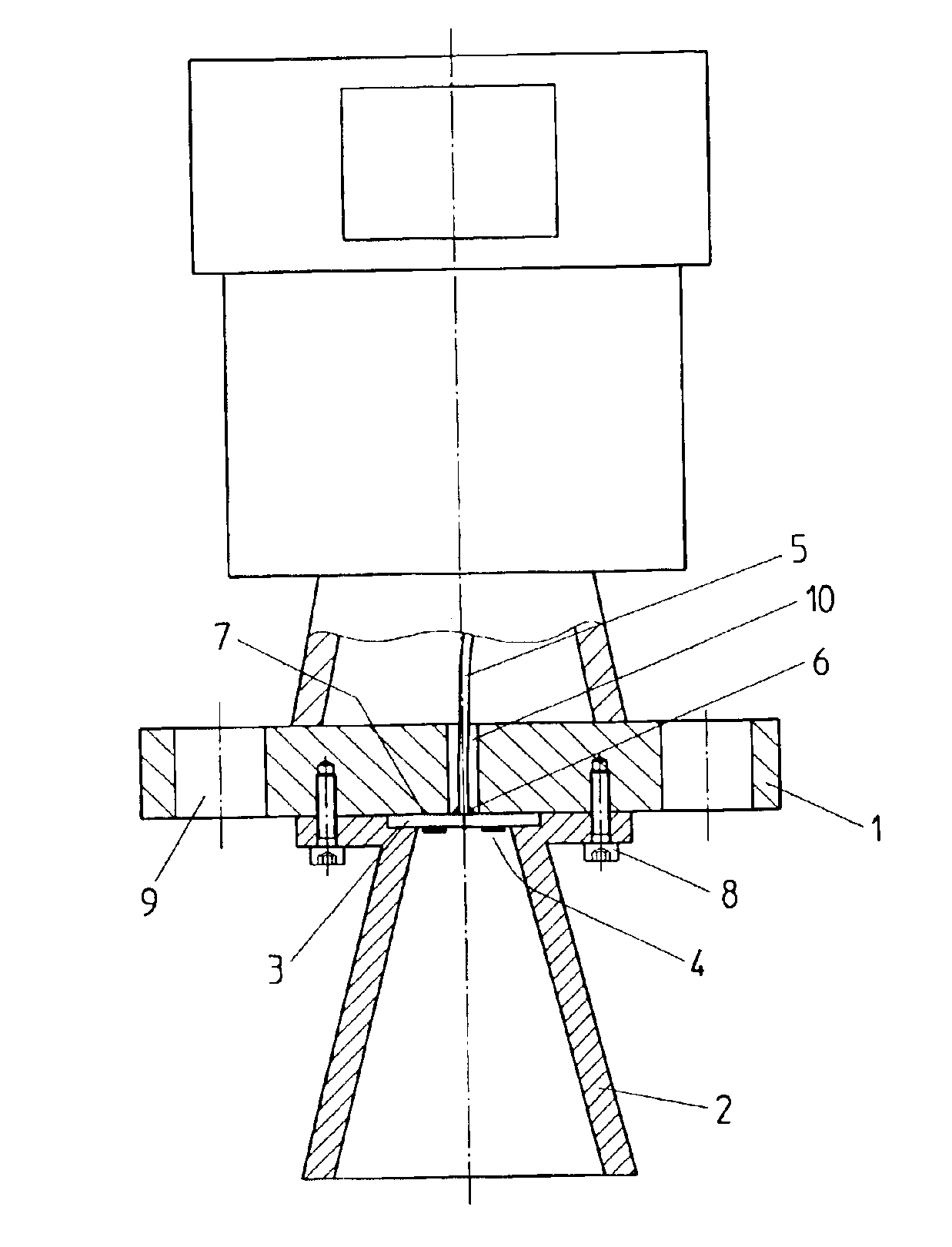
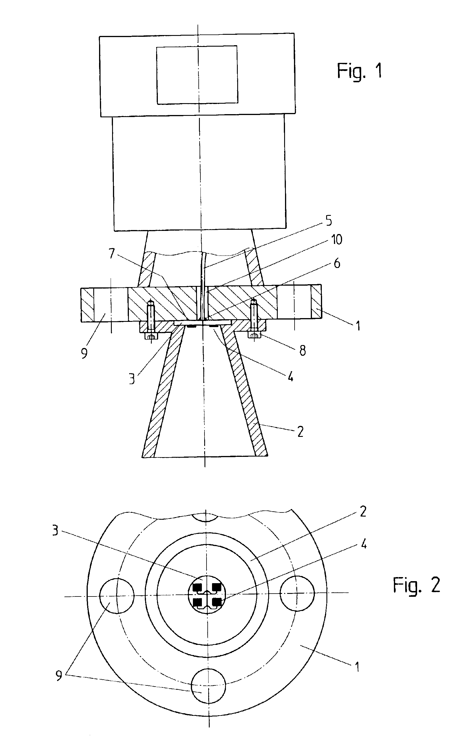
[0040]FIG. 1 is a longitudinal cut through an inventive antenna system. The antenna system is comprised of a metallic flange 1, which is provided with a plurality of bores 9. The bores 9 serve for receiving screws by means of which the antenna system is to be attached on a receptacle or storage tank (not shown) having an aperture through which the metallic antenna horn 2 protrudes into the inner receptacle space. The bores 9, for this purpose, have to find their continuation in corresponding bores in the receptacle wall, so as to allow the antenna system to be screwed with the receptacle. Moreover, flange 1 has a further bore 10 in its center, through which a coaxial cable 5 is guided. Below flange 1 of the antenna system, an antenna horn 2 is attached with screws 8.

[0041]The antenna horn 2 is fixed on flange 1 in such a manner that the center axis of the antenna horn 2 is coaxial to the center axis of bore 10. Antenna horn 2 features a recess at the front side of its small funnel o...


PUM


Abstract

The present invention relates to an antenna system for a level measuring device for emitting microwaves by means of an antenna horn, at the front side of the small funnel aperture thereof. HF energy in the form of microwave signals is directly axially coupled by means of planar structures having one patch or several patches.

Description

CROSS REFERENCE TO RELATED APPLICATIONS[0001]The present application is a continuation-in-part of U.S. provisional application Ser. No. 60 / 333,440, filed Nov. 26, 2001, which is expressly incorporated herein, in its entirety, by reference.FIELD OF THE INVENTION[0002]The present invention relates to an antenna system for a level measuring device suited for the contact-free measurement of filling levels. Such an antenna system is in particular destined for being used with a so-called filling level radar device and a radar level transmitter, respectively. Such devices are also often called radar level sensor. Furthermore, the present invention relates to a filling level radar comprising such an antenna system. In general, antenna systems of the kind mentioned above are used to emit microwave signals. The emission of the microwave signals can be carried out non-continuously or continuously. Non-continuously emitted signals are for example microwave pulses. Radar level sensors emitting c...

Claims


Application Information

Patent Timeline
Patent Type & Authority Patents(United States)
IPC IPC(8): G01F23/284A61P37/02
CPCG01F23/284A61P37/02
Inventor KIENZLE, KLAUSMOTZER, JURGENSCHULTHEISS, DANIELFEHRENBACH, JOSEF
Owner VEGA GRIESHABER GMBH & CO
Learn More