Antenna system for a level measurement apparatus

a level measurement and level measurement technology, applied in the direction of antennas, engine lubrication, liquid/fluent solid measurements, etc., can solve the problems of large constructional space, large system dimensions, and difficulty in accurately matching waveguide dimensions to the transmission frequency range of microwave signals

Inactive Publication Date: 2003-08-14
VEGA GRIESHABER GMBH & CO
View PDF7 Cites 73 Cited by
  • Summary
  • Abstract
  • Description
  • Claims
  • Application Information

AI Technical Summary

Benefits of technology

[0011] Thus, in an inventive antenna system according to one of the above mentioned aspects of the invention, a waveguide is for the first time dispensed of, into which microwave signals have been coupled to date, whereby the longitudinal extension of the antenna system can be reduced. Instead of the waveguide for example a coaxial cable my be connected to the planar structure with for example the at least one patch on it to conduct microwave signals (e.g. microwave pulses) from a microwave unit of the radar sensor generating microwave signals to the antenna system according to the present invention such that microwaves are emitted in the direction of a product of which the level has to be measured. One advantage of the present invention may be that the antenna system is more compact and is small enough to be used even under very constricted space conditions.
[0012] Such as has already been described, it might has been common usage to couple microwaves--either by means of an exciter pin or using patches--into a waveguide followed by an antenna horn. This coupling into a waveguide originally was necessary in a construction-contingent manner due to the lateral arrangement of the exciter pin. With the further development of this system using, instead of the exciter pin, planar structures for coupling in the microwaves, the principle of coupling into a waveguide was maintained, since the experts thought that this would be necessary for a perfect function of the system.
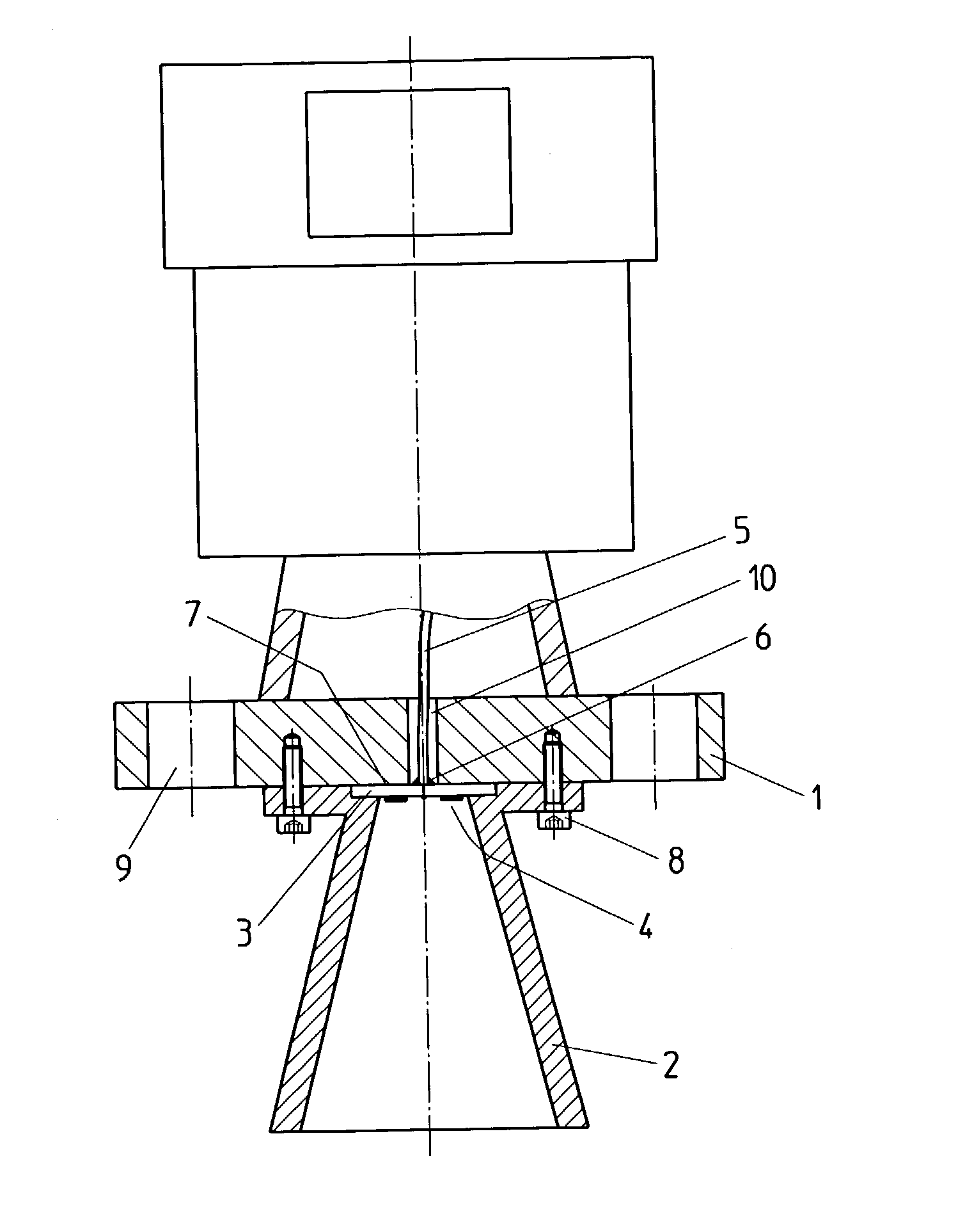
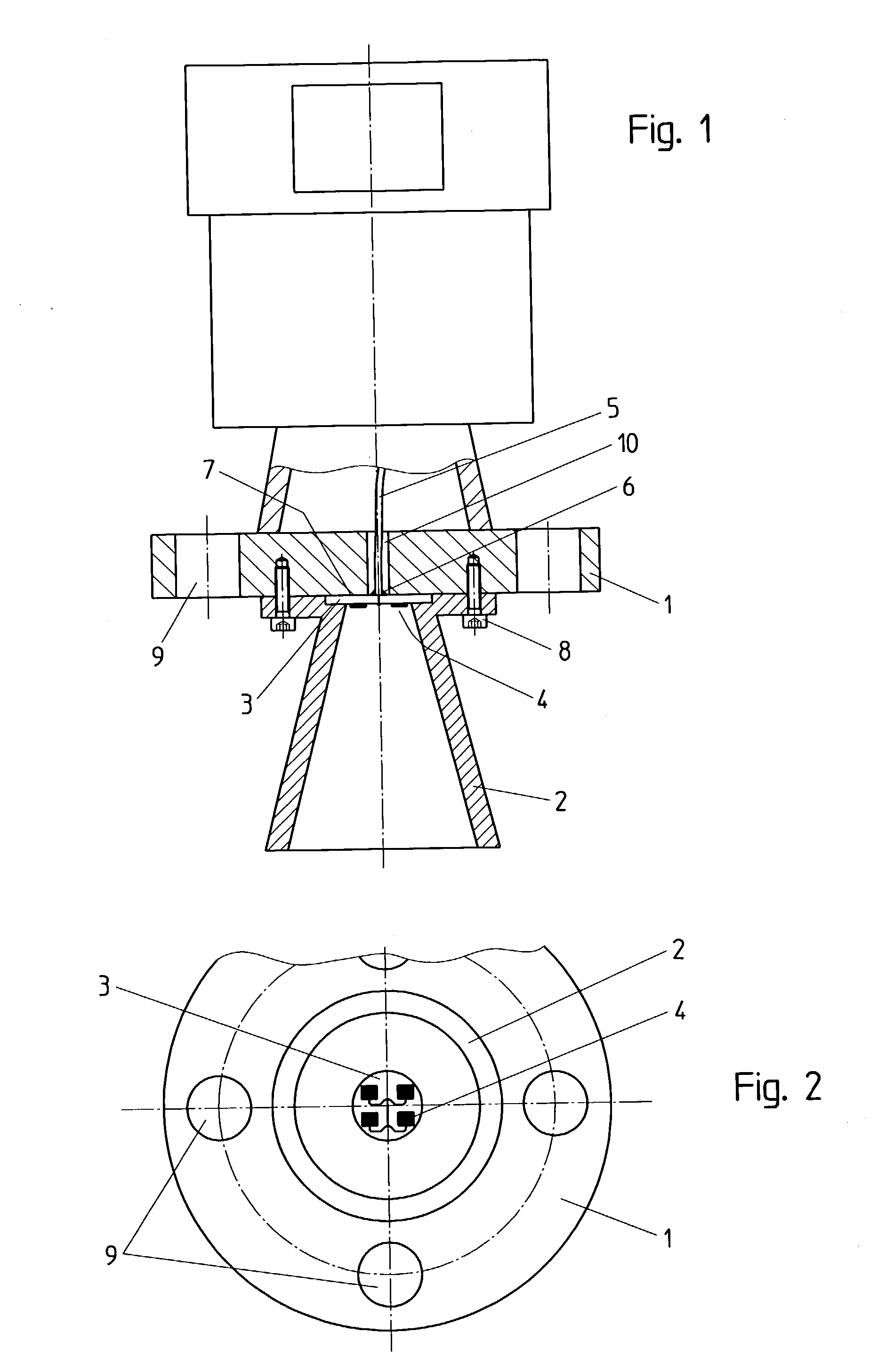
[0013] The combination of a waveguide and an antenna horn, however, required an important component extension in the longitudinal direction. Surprisingly, it was found after conducting extensive tests that it is possible to couple HF energy in the form of microwaves by means of a planar structure (patch) directly into an antenna horn, e.g. in the zone of the horn flaring. According to an exemplary embodiment of the present invention planar structures with two or four, may even more rectangular patches optimized for a frequency of 26 GHz have turned out to be particularly suited. The hereby used patches can also have any other shapes, such as, for example, triangular, oval or circular shapes. For enabling a direct coupling, the patches may be arranged directly at the antenna horn front end. Through this direct coupling into the antenna horn, the constructional length of the antenna system is reduced by up to 60% as compared to conventional systems. The length of a prior art 2" antenna with a waveguide at a frequency of 26 GHz, for example, is about 160 mm, whereas the configuration of the novel claimed features is only 65 mm at comparable electric properties.
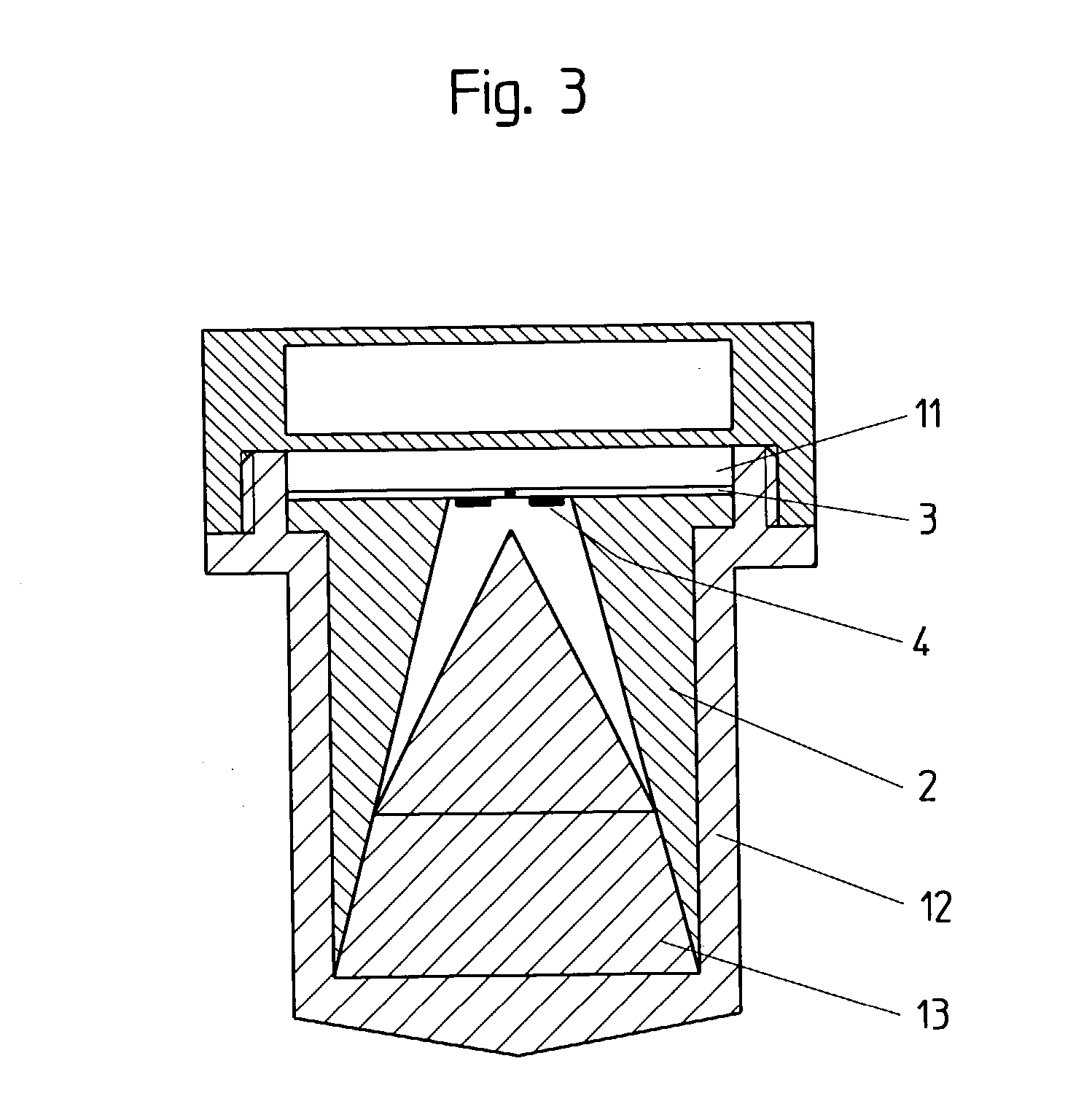
[0014] Antennas are often used in chemically aggressive environmental conditions or in the food sector. For protecting the patches from a possible chemical action or from getting dirtied by foodstuffs, inventive antenna systems are preferably filled completely or in part with a dielectric material. This filling with a dielectric material (e.g. PP, PVDF, PTFE, ceramic or mixtures thereof) having a dielectric constant of .epsilon..sub.2.gtoreq.1, apart from the protection from a chemical action and a dirtying of the patch, has also a mechanically abrasive protective effect, which can be very useful with certain filling products. Moreover, it is to be stated here that by filling the horn antennas with a dielectric material, the condensate is at the same time prevented from penetrating into the inner antenna space.
[0015] Filling the antenna with a dielectric material, however, serves a completely different purpose: apart from the purely protective effect resulting for the antenna, the use of such a filling allows for further reducing the size of the antenna system in that the radiation surface of the filling is given the form of an optical lens or a cone, whereby the wave propagation angle can be reduced. This corresponds simultaneously to the achievement of a higher gain of an inventive antenna system as compared to a conventional antenna having altogether the same properties. Apart from the plain advantage of achieving a higher gain, the use of a dielectric filling medium thus allows for the size reduction of the antenna: By the fact that due to the lens or cone form of the filling medium the wave propagation angle is reduced and the wave signal is therewith less scattered than it is usual with patch antennas, the number of the necessary patches can be reduced for achieving a determined predefined gain. This, however, in turn entails a reduction in the antenna size--above all in the diameter thereof.
[0016] Thus, by focussing the free-space wave coupled in by the patches effected by the antenna horn and the dielectric material present in the antenna horn, the reduction of the number of patches required for achieving a certain gain may be possible. Preferably, four separate patches are used, which are electrically coupled to each other. Hence, it is likewise possible to use only one, two, or more than four patches.

Problems solved by technology

Horn antennas are already known from prior art in the field of the filling level measuring technology; however, all of them exhibit certain problems due to their constructional configuration and length.
This solution, however, is again based on the construction-inherent problem that such an antenna system requires a large constructional space--which is mainly extended in the longitudinal direction.
Hereby, the exact matching of the waveguide dimensions to the transmission frequency range of the microwave signal is problematic for allowing only the fundamental mode of wave to propagate within the waveguide.
Matching adjustments for the waveguide, which are not exact enough, can lead to signal distortions due to wave dispersion, eventually resulting in a misrepresented measurement result.
In the frequency range of over 30 or 50 GHz, the mechanical dimensions of a waveguide usually become so small that a conventional construction can no longer be operated.

Method used


Image

  • Antenna system for a level measurement apparatus
  • Antenna system for a level measurement apparatus
  • Antenna system for a level measurement apparatus

Examples


Embodiment Construction

[0040] FIG. 1 is a longitudinal cut through an inventive antenna system. The antenna system is comprised of a metallic flange 1, which is provided with a plurality of bores 9. The bores 9 serve for receiving screws by means of which the antenna system is to be attached on a receptacle or storage tank (not shown) having an aperture through which the metallic antenna horn 2 protrudes into the inner receptacle space. The bores 9, for this purpose, have to find their continuation in corresponding bores in the receptacle wall, so as to allow the antenna system to be screwed with the receptacle. Moreover, flange 1 has a further bore 10 in its center, through which a coaxial cable 5 is guided. Below flange 1 of the antenna system, an antenna horn 2 is attached with screws 8.

[0041] The antenna horn 2 is fixed on flange 1 in such a manner that the center axis of the antenna horn 2 is coaxial to the center axis of bore 10. Antenna horn 2 features a recess at the front side of its small funnel...


PUM


Abstract

The present invention relates to an antenna system for a level measuring device for emitting microwaves by means of an antenna horn (2), at the front side of the smaller funnel aperture thereof, HF energy in the form of microwave signals is directly axially coupled by means of planar structures having one patch or several patches (4).

Description

[0001] The present application is a continuation-in-part of U.S. provisional application Serial No. 60 / 333,460, filed Nov. 26, 2001, which is expressly incorporated herein, in its entirety, by reference.[0002] The present invention relates to an antenna system for a level measuring device suited for the contact-free measurement of filling levels. Such an antenna system is in particular destined for being used with a so-called filling level radar device and a radar level transmitter, respectively. Such devices are also often called radar level sensor. Furthermore, the present invention relates to a filling level radar comprising such an antenna system. In general, antenna systems of the kind mentioned above are used to emit microwave signals. The emission of the microwave signals can be carried out non-continuously or continuously. Non-continuously emitted signals are for example microwave pulses. Radar level sensors emitting continuously microwaves are often called FMCW (frequency m...

Claims


Application Information

Patent Timeline
Patent Type & Authority Applications(United States)
IPC IPC(8): A61P37/02G01F23/284
CPCG01F23/284A61P37/02
Inventor KIENZLE, KLAUSMOTZER, JURGENSCHULTHEISS, DANIELFEHRENBACH, JOSEF
Owner VEGA GRIESHABER GMBH & CO
Why Eureka
Try Eureka