Antenna device for radar-based level gauging

Inactive Publication Date: 2004-06-10
ROSEMOUNT TANK RADAR
View PDF7 Cites 43 Cited by
  • Summary
  • Abstract
  • Description
  • Claims
  • Application Information

AI Technical Summary

Problems solved by technology

Using an opening at some arbitrary position might not be possible since locations where internal tank structures may give disturbing radar echoes have to be avoided.
Obviously, the three requirements may not always be complied with, e.g. when the first two requirements imply an antenna size, which is larger than the only suitable opening.
This, however, obviously requires a tank environment allowing a person to enter for the necessary mounting work.
Due to the end-fire nature of the rod antenna this is hard to imp

Method used


Image

  • Antenna device for radar-based level gauging
  • Antenna device for radar-based level gauging
  • Antenna device for radar-based level gauging

Examples


Embodiment Construction

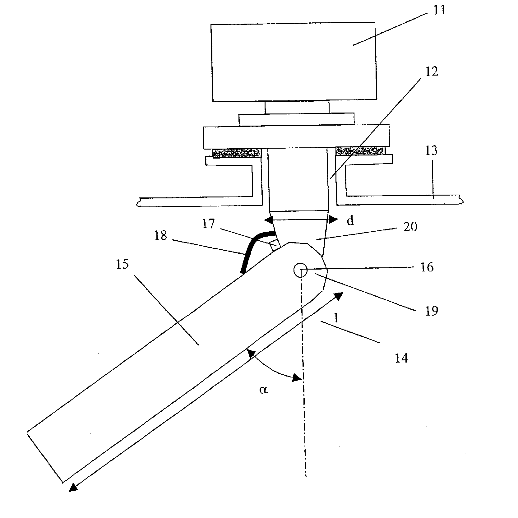
[0037] With reference to FIG. 1, which schematically illustrates, in a side view, an apparatus aimed for radar-based level gauging, a preferred embodiment of the present invention will be described. The apparatus may be a frequency modulated continuous wave (FMCW) radar apparatus, a pulsed radar apparatus, or any other type of distance measuring radar.

[0038] Many frequencies can be used for radar level gauging but bands close to 5.8, 10 and 25 GHz have been used so far. In tanks where foam and contamination are frequent the lowest one of said frequencies is most common since the microwave signal at this frequency is much less sensitive for such degradations. The present invention is particularly useful for this frequency, or even lower frequencies, as it is difficult to obtain a narrow radiation beam with a conventional antenna solution.

[0039] The radar-based level gauge, denoted by 11 in FIG. 1, is mounted above an opening 12 of a roof 13 of a tank or container filled with matter, ...


PUM


Abstract

An antenna device in a radar-based level gauge mounted at an opening in a roof of a tank, the antenna device comprising at least one elongated radiating structure, which has a length that is substantially larger, preferably more than 3-5 times longer, than a maximum cross-sectional length dimension of the opening; is oriented in a non-vertical position; and is configured and fed to produce an essentially vertical radiation beam directed downwards in the tank. Preferably, the antenna device is foldable and is inserted into the tank through the opening and oriented in the non-vertical position by means of folding the radiating structure.

Description

[0001] The invention relates generally to level gauging, and more specifically the invention relates to antenna devices for use in radar-based level gauging equipment, and to the mounting of such antenna devices.BACKGROUND OF THE INVENTION AND RELATED ART[0002] Radar-based methods are since several years commonly used for level gauging in various tanks. The antenna devices used for transmitting and receiving the radar signals, are critical parts and a few different antenna types have been employed.[0003] Three basic factors to consider for an antenna for radar-based level gauging are gain, antenna pattern, and size.[0004] The antenna gain, which is closely related to the efficient antenna area, has to be high enough to provide for receiving a sufficiently strong signal echo from the required maximum distance. For a circular antenna the maximum measuring distance is, in the limiting case where the liquid surface is turbulent, proportional to the antenna diameter.[0005] Further, the r...

Claims


Application Information

Patent Timeline
IPC IPC(8): G01F23/284H01Q1/08H01Q1/12H01Q13/20H01Q13/22H01Q15/20H01Q19/10H01Q19/24H01Q21/00
CPCG01F23/284H01Q1/08H01Q1/1264H01Q13/206H01Q21/0043H01Q15/20H01Q19/106H01Q19/24H01Q13/22
Inventor EDVARDSSON, KURT OLOV
Owner ROSEMOUNT TANK RADAR
Why Eureka
Try Eureka