Pump block tilter

A technology for turning over machines and pump bodies, which can be applied to assembly machines, metal processing equipment, manufacturing tools, etc. It can solve problems such as damage to pump bodies, personnel damage, and low efficiency, and achieve increased assembly speed, reduced labor intensity, and reduced safety risks Effect

Active Publication Date: 2013-08-28
FLOWSERVE FLUID MOTION & CONTROL SUZHOU
View PDF6 Cites 1 Cited by
  • Summary
  • Abstract
  • Description
  • Claims
  • Application Information

AI Technical Summary

Problems solved by technology

[0003] Centrifugal pumps are widely used. In the prior art, the centrifugal pump needs to be turned over during the assembly process. During assembly, the staff needs to turn over the pump body. The pump body is relatively heavy. High risk, often resulting in personal injury or damage to the pump body

Method used


Image

  • Pump block tilter
  • Pump block tilter

Examples


Embodiment Construction

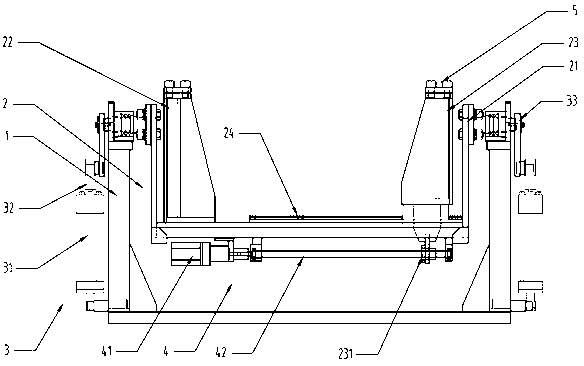
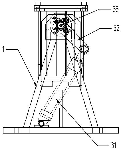
[0015] See figure 1 with figure 2 As shown, the present invention provides a pump body turning machine for clamping and turning the pump body. In particular, the pump body turning machine includes a bracket 1, a clamping unit 2 and a turning unit 3. The clamping unit 2 uses the bracket 1 as The fulcrum is axially connected with the turning unit 3, and the clamping unit 2 fixes and clamps the pump body and is driven by the turning unit 3. The clamping unit 2 turns 360° under the driven state to achieve the effect of the pump body turning.

[0016] Among them, the clamping unit 2 includes a bracket 21, a clamping column 22, a mobile clamping column 23 and a sliding rail 24, the clamping column 22 and the sliding rail 24 are fixedly attached to the bracket 21, and the mobile clamping column 23 is movably attached On the slide rail 24, the pump body is slidably clamped by moving the clamping column 23. Both the clamping column 22 and the moving clamping column 23 are provided with a...


PUM


Abstract

The invention discloses a pump block tilter used for clamping a tilting pump block. Particularly, the pump block tilter comprises a support, a clamping unit and a tilting unit. The clamping unit is connected with the tilting unit through shafts by being supported by the support. The clamping unit is used for tightly clamping the pump block and is driven by the tilting unit. The clamping unit tilts by 360 degrees when driven. The pump block tilter is used for tilting pump blocks in assembly process. Through the structure that the clamping unit is driven to tilt by pneumatic links, pump block tilting is achieved, labor of staff is less intense, pump assembly is faster, safety risks are less, and work efficiency is improved effectively.

Description

Technical field [0001] The invention relates to a pump body turning machine, in particular to a turning machine which clamps a fixed centrifugal pump for turning. Background technique [0002] Centrifugation is a manifestation of the inertia of an object. The centrifugal pump is designed according to this principle. The high-speed rotating impeller blades drive the water to rotate and throw the water out to achieve the purpose of transportation. The main flow parts of centrifugal pumps are suction chamber, impeller and pressurized water chamber. The suction chamber is located in front of the water inlet of the impeller, and plays the role of guiding the liquid to the impeller; the pressurized water chamber mainly has three forms: spiral pressurized water chamber (volute type), guide vane and space guide vane; the impeller is the most advanced pump. The important working element is the heart of the flow component. The impeller consists of a cover plate and a middle blade. [0003]...

Claims


Application Information

Patent Timeline
Patent Type & Authority Applications(China)
IPC IPC(8): B23P21/00
Inventor 薛文玲
Owner FLOWSERVE FLUID MOTION & CONTROL SUZHOU
Why Eureka
Try Eureka