
A lock body processing machine tool

A technology for processing machine tools and lock bodies, which is applied in the direction of metal processing machine parts, metal processing, metal processing equipment, etc., can solve the problems of low processing efficiency, high processing cost, and difficult to guarantee processing accuracy, so as to improve chamfering efficiency, The effect of eliminating rotation error and improving processing efficiency and processing accuracy

Active Publication Date: 2016-01-20
HANGZHOU XINZHIYUAN CNC EQUIP
View PDF4 Cites 0 Cited by
  • Summary
  • Abstract
  • Description
  • Claims
  • Application Information

AI Technical Summary

Problems solved by technology

In the prior art, the above-mentioned processes are all processed by separate equipment, the processing efficiency is low, the processing accuracy is not easy to guarantee, and the processing cost is also high

Method used


Image

  • A lock body processing machine tool
  • A lock body processing machine tool
  • A lock body processing machine tool

Examples


Embodiment Construction

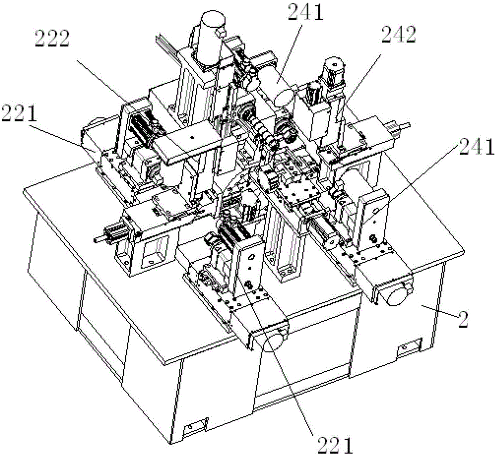
[0034] Figure 2 to Figure 3 The specific structure of the lock body processing machine tool is shown, which includes a bed 2, a turntable is provided at the center of the bed, and four lock body fixtures 13 are arranged at intervals of 90 degrees on the turntable, and the bed is arranged in a sequence around the turntable. In the clockwise direction, a material cutting device 21, a drilling device 22, a material unloading device 23 and a chamfering device 24 are sequentially arranged, wherein the material cutting device 21 is used for cutting off the lock body blank and cutting the breaking groove 30 of the lock body. Open, the drilling device 22 is used to drill out the lock core hole 31 and the through hole 32, the chamfering device 24 is used to chamfer the lock core hole 31 and the through hole 32, and the described unloading device 23 will lock The body is removed from the lock body fixture.

[0035] The material cutting device 21 includes a material cutting frame 210 t...


PUM


Abstract

The invention discloses a lock machining machine tool comprising a machine tool body. A rotary table is arranged at the center of the machine tool body; four lock clamps are arranged on the rotary table at 90-degree intervals; the machine tool body is provided with a cutting device, a drilling device, a discharging device and a chamfering device sequentially clockwise around the rotary table; the cutting device is used for cutting off a lock blank and cutting a disconnection groove of a lock apart; the drilling device is sued for drilling a lock cylinder hole and a through hole; the chamfering device is used for chamfering the lock cylinder hole and the through hole; and the discharging device is used for discharging the lock from the lock clamps. Machining of most processes of locks is achieved through one machine tool, and machining efficiency and machining accuracy are improved.

Description

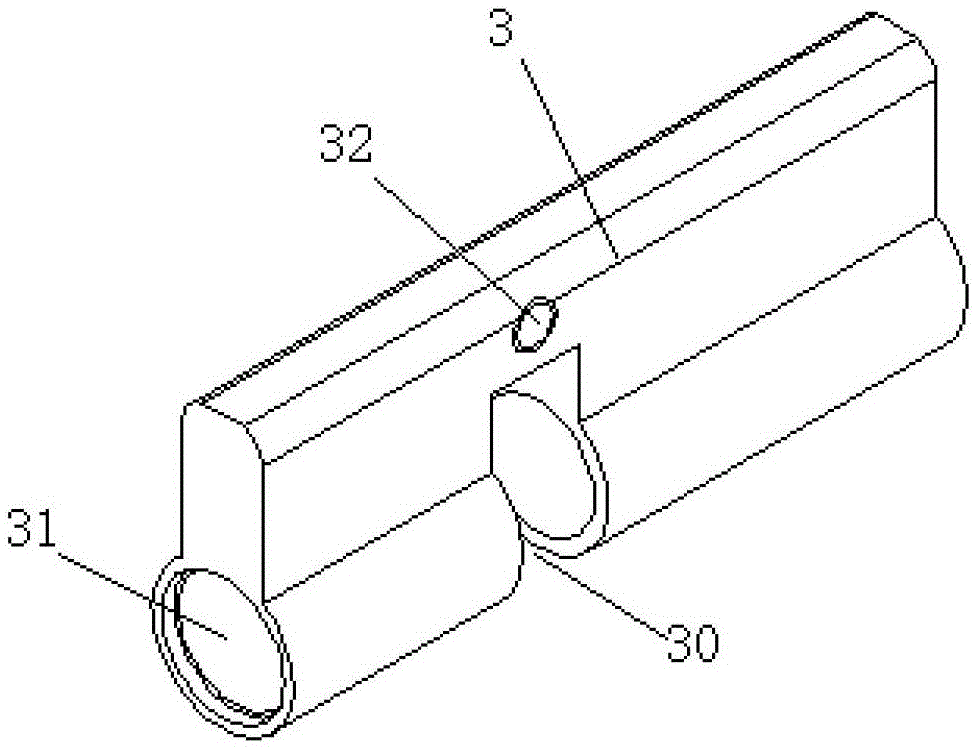
technical field [0001] The invention relates to a pin lock processing machine. Background technique [0002] Such as figure 1 As shown, the bottom of the lock body 3 of the tumbler lock is provided with a through lock cylinder hole 31, and at the same time, a disconnection groove 30 is provided in the middle of the bottom of the lock body to separate the lock cylinder hole into two ends, and the top of the lock body is provided with a hole above the disconnection groove. The through hole 32 perpendicular to the lock core hole, the through hole and the lock core hole aperture all need to be chamfered, and the lock body needs to be cut to a suitable length before opening the break groove and the lock core hole. In the prior art, the above-mentioned processes are all processed by separate equipment, the processing efficiency is low, the processing accuracy is not easy to guarantee, and the processing cost is also high. Contents of the invention [0003] The technical proble...

Claims


Application Information

Patent Timeline
Patent Type & Authority Patents(China)
IPC IPC(8): B23P23/00B23Q3/08B23Q7/06B23Q1/25
Inventor 甄健松
Owner HANGZHOU XINZHIYUAN CNC EQUIP
Learn More