Mold with pressurizing connecting rod structure

A connecting rod structure and mold technology, which is applied in external support, transportation packaging, packaging, etc., to achieve the effect of improving working stability, good working stability and low working noise

Inactive Publication Date: 2013-08-28
浙江诚达机械股份有限公司
View PDF7 Cites 2 Cited by
  • Summary
  • Abstract
  • Description
  • Claims
  • Application Information

AI Technical Summary

Problems solved by technology

[0003]In the current paper-plastic packaging machine, flat blister packaging machine and other equipment, thermoforming, heat sealing, cutting or heat sealing and cutting molds are used, thermoforming, Heat sealing, cutting and heat sealing and cutting molds usually include a mold base and an upper mold and a lower mold set in the mold base. Their common feature is that the contact pressure of the upper and lower molds is large during work. In order to ensure the contact pressure, the upper mold and the lower mold The movement of the mold needs to be driven by the cam or the pressurized cylinder. The disadvantage is that the working noise is large and the working stability is poor.
The applicant once designed a thermoforming mechanism of a paper-plastic machine driven by a crank and cylinder structure, and applied for a patent on June 17, 2011, the patent number: 201120205408.4, the patent name "Heat-sealing mechanism of a paper-plastic packaging machine 》, but the structure is relatively complicated, and it has not achieved the desired technical effect

Method used


Image

  • Mold with pressurizing connecting rod structure
  • Mold with pressurizing connecting rod structure

Examples


Embodiment Construction

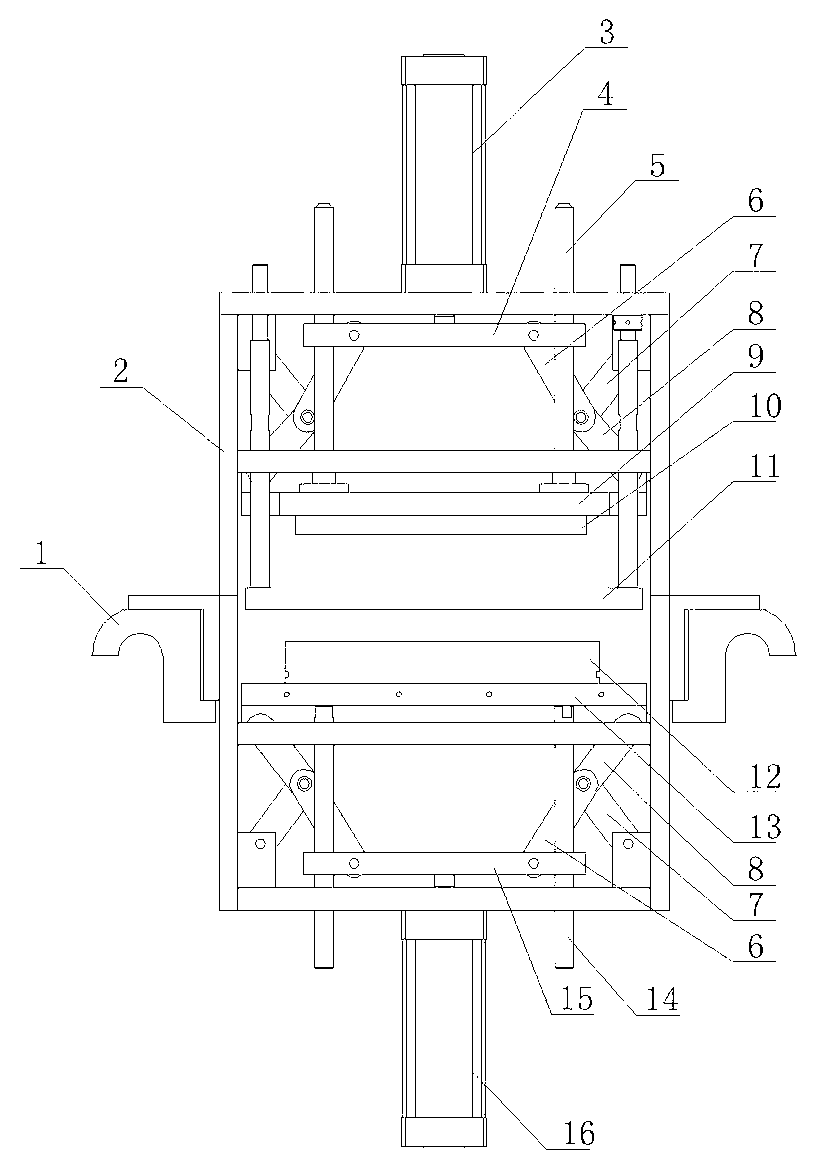
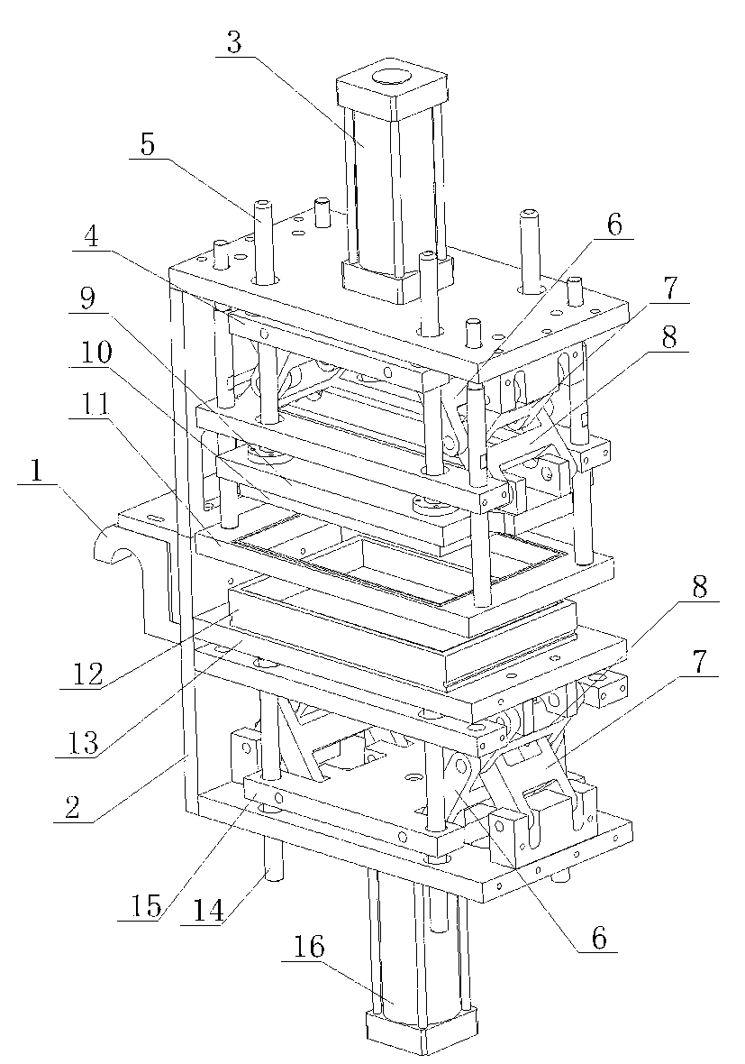
[0013] As shown in the figure, the mold with a pressurized connecting rod structure of the present invention is a thermoforming mold, including a mold base 2, an upper mold 10 and a lower mold 12, and a stripping plate 11 is arranged between the upper mold 10 and the lower mold 12 , the movement of the lower mold 12 in the mold frame 2 is promoted by the lower link device. The lower link device includes a top plate 13, a bottom plate 15 and a connecting rod member. Located below the top plate 13 and pushed by the lower cylinder 16, the connecting rod member is provided with two groups of left and right symmetry. The connecting rod member is composed of a main push rod 6, a swing rod 7 and a driven rod 8. One end of the driven rod 8 is hingedly connected with the pin shaft, and the other end is hingedly connected with the bottom plate 15, the formwork 2 and the top plate 13 respectively; the movement of the upper mold 10 in the formwork 2 is driven by the upper link device, and ...


PUM


Abstract

The invention discloses a mold with a pressurizing connecting rod structure. The mold comprises a die frame, and an upper die and a lower die, which are arranged inside the die frame, and the mold is characterized in that the upper die, the lower die or the upper die and the lower die are pushed by a connecting rod device to move inside the die frame, the connecting rod device comprises a top plate for installing the upper die or the lower die, a soleplate and connecting rod components, the up-down movement of the top plate and the soleplate is guided through a guide column, two groups of connecting rod components in lateral symmetry are provided, each connecting rod component consists of a main push rod, a swinging rod and a driven rod, one ends of the main push rod, the swinging rod and the driven rod are hinged together through a pin shaft, the other ends are respectively hinged with the soleplate, the die frame and the top plate, the soleplate is pushed by an air cylinder, when the upper die and the lower die are closed, the swinging rod and the drive rod are respectively straightened, and the swinging rod and the driven rod are connected into a straight line. Compared with the traditional thermal forming, thermal sealing, cutting or thermal sealing cutting mold, the mold is more reasonable in structure design, simple in structure, low in working noise and high in working stability.

Description

[0001] technical field [0002] The invention relates to a mold with a booster connecting rod structure. Background technique [0003] In the current paper-plastic packaging machine, flat blister packaging machine and other equipment, thermoforming, heat sealing, cutting or heat sealing and cutting molds are used. Thermoforming, heat sealing, cutting and heat sealing and cutting molds usually include mold bases and The upper mold and the lower mold set in the mold base have a common feature: the contact pressure of the upper and lower molds is large during work. In order to ensure the contact pressure, the movement of the upper mold and the lower mold must be driven by a cam or a booster cylinder. The disadvantage is The working noise is loud and the working stability is poor. The applicant once designed a thermoforming mechanism of a paper-plastic machine driven by a crank and cylinder structure, and applied for a patent on June 17, 2011, the patent number: 201120205408.4...

Claims


Application Information

Patent Timeline
Patent Type & Authority Applications(China)
IPC IPC(8): B65B51/10
Inventor 苏宗荣谢世晨陈圣禹叶世友
Owner 浙江诚达机械股份有限公司
Why Eureka
Try Eureka