Inserted type locking and buckling floor

A plug-in, floor technology, applied in the direction of floors, buildings, coatings, etc., can solve problems such as deterioration of coordination, damage to a single floor, and impact on service life, achieving low manufacturing costs, simple structure, and extended service life Effect

Active Publication Date: 2015-05-13
DER FUTURE SCI & TECH HLDG GRP CO LTD
View PDF5 Cites 0 Cited by
  • Summary
  • Abstract
  • Description
  • Claims
  • Application Information

AI Technical Summary

Problems solved by technology

However, this kind of floor needs to mill out the lock structure on the material itself to lock each other. When installing, it needs to be inserted at a certain angle and accompanied by a certain material deformation. Some also need to be knocked for installation, which is easy to cause damage to the floor. , affecting its service life
[0003] For this reason, CN102383572A discloses a plug-in lock floor, which uses a lock structure and cooperates with a lock bar to insert and self-lock, making the installation of the floor more convenient. Moreover, it will not cause damage and deformation during the installation process, which facilitates the installation and is also conducive to ensuring the quality of the floor; however, although the uppermost layer of such a floor system is usually made of waterproof or impermeable materials, it can be used in the composition of the ground covering system. At the joints of adjacent floor covering panels, the floor covering system may be susceptible to water damage
Fittings (joints) between adjacent floorboards, such as the chamfers of plug-in locking floorboards11, may allow water or other liquids to penetrate into the joints between the floorboards, resulting in damage, twisting, accelerated Wear or deterioration of fit

Method used


Image

  • Inserted type locking and buckling floor
  • Inserted type locking and buckling floor

Examples


Embodiment 1

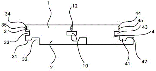
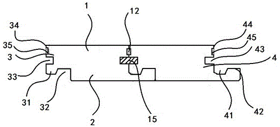
[0024] Such as Figure 1-2As shown, the plug-in locking floor in this embodiment includes a plurality of identical floor units, and the floor units include: a generally flat first surface 1, and a second surface opposite to the first surface 1 surface 2; a first side end 3, and a second side end 4 opposite to the first side end 3, and each side end extends respectively from between said first and second surfaces; said first side end 3 has a downwardly protruding male tenon 31 and a male card groove 32 adjacent to the male tenon 31; at the second side end 4 there is an upwardly protruding female tenon 41 and a female card groove adjacent to the female tenon 41 42. The male tenon 31 and the male card groove 32 of the first side end 3 are engaged with the female card groove 41 and the female tenon 42 of the second side end 4 of the adjacent floor unit respectively, and form at least a partially contacted contact surface; Wherein, the first side end 3 is located above the male te...


PUM


Abstract

The invention relates to an inserted type locking and buckling floor which comprises a plurality of floor single bodies. Each floor single body comprises a flat first surface, a second surface, a first side end and a second side end. Each side end extends from the portion between the first surface and the second surface. The first side end is provided with a male tenon protruding downwards and a male clamping ditch adjacent to the male tenon. The second side end is provided with a female tenon protruding upwards and a female clamping ditch adjacent to the female tenon. A male clamping groove is formed in the portion, above the male tenon, of the first side end and a female clamping groove is formed in the portion, above the female clamping ditch, of the second side end. The male clamping groove of the first side end is matched with the female clamping groove of the second side end of an adjacent floor single body, so that an inserting groove is formed, and a locking bar is arranged and matched with the inserting groove. According to the inserted type locking and buckling floor, installation of floors is convenient, the floor single bodies do not need to be inserted by a certain angle and knocked, waterproof performance is good, deformation and damage are avoided, and the service life of the inserted type locking and buckling floor is prolonged.

Description

technical field [0001] The invention relates to a floor used in commercial, industrial or household environments, in particular to a plug-in locking floor with waterproof function. Background technique [0002] At present, flooring has been widely used in homes and various public places as a building decoration material. Existing floors are generally flat strip floors, and adjacent ones are connected and laid by engaging structures. The early floors were mainly solid wood floors. With the development of science and technology, more high-strength laminate floors have been used. This kind of floor has uniform texture and high strength. In order to facilitate the installation and maintenance of the floor, various forms of assembled floors have appeared, which generally have a tenon and tongue-and-groove structure. The common form of this kind of floor with a tongue-and-groove structure is the flat buckle type, that is, a rectangular tenon and a tongue and groove are set in the...

Claims


Application Information

Patent Timeline
Patent Type & Authority Patents(China)
IPC IPC(8): E04F15/02C09D4/06C09D7/12
Inventor 吴元新
Owner DER FUTURE SCI & TECH HLDG GRP CO LTD
Why Eureka
Try Eureka