

Roller system of louver pin shaft roller mechanism and incomplete gear overturning mechanism
A technology of rolling wheels and gears, applied in the field of variable-pitch combined shutters, can solve problems such as unpublished transmission mechanisms
- Summary
- Abstract
- Description
- Claims
- Application Information
AI Technical Summary
Problems solved by technology
Method used
Image

Examples
Embodiment 1
[0109] Embodiment 1: Rotor reel system of variable pitch combined louver with three louver blades
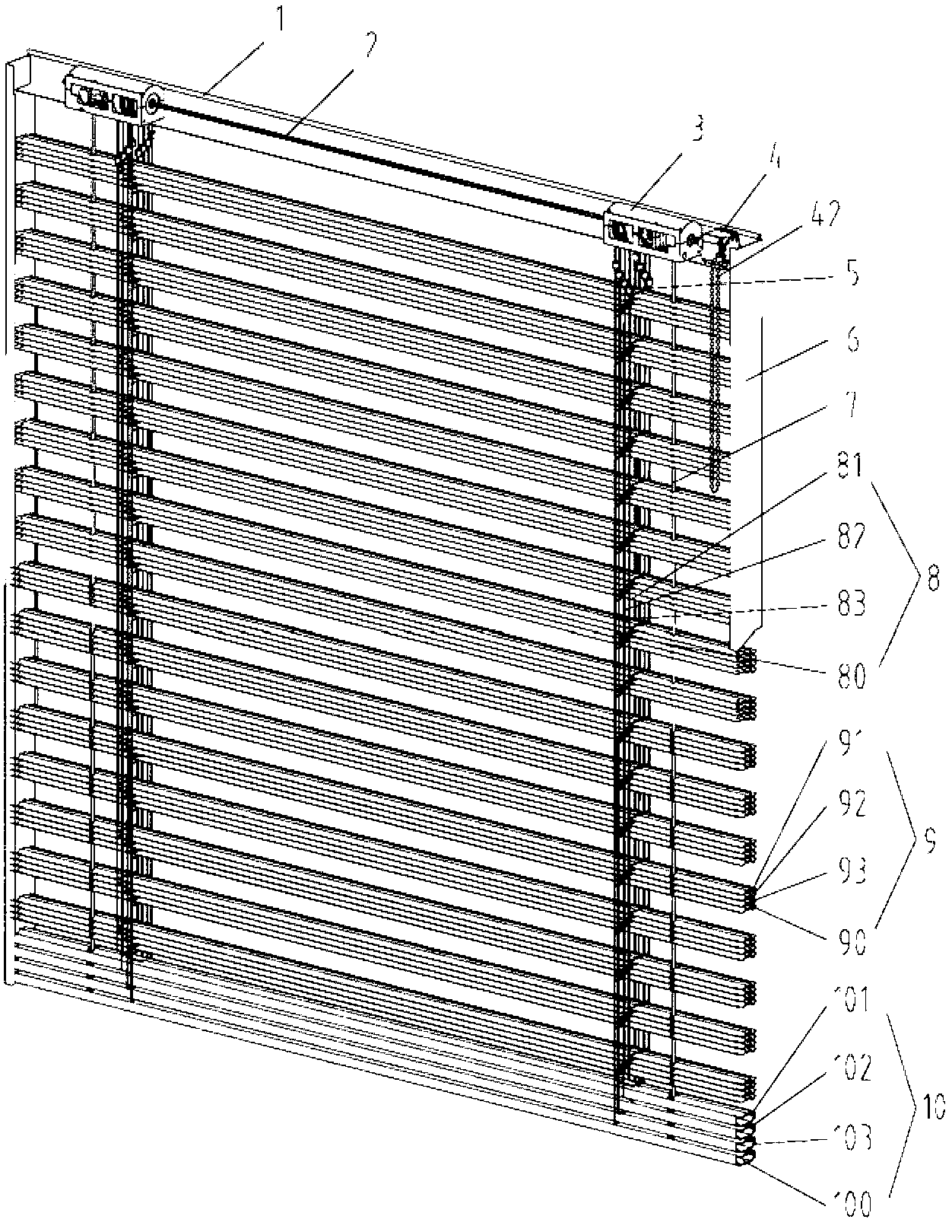
[0110] A movement cycle of the relative lifting and turning of the louvers of the variable-pitch combined louvers with three louvers is: (1) The main louvers 90 are distributed on the window at equal pitches, and the secondary louvers 91, 92 and 93 are stacked on the main On the louvers 90, (corresponding to Figure 75a ), (2) The second hundred blades 91 rise to D relative to the main shutter blades 90 1 -D 2 position, the second two louver blades 92 and the second three louver blades 93 are still superimposed on the main louver blade 90 (corresponding to Figure 75b ), (3) the second hundred blades 91 continue to rise to D relative to the main shutter blades 90 2 position, while the second louver 92 rises to D relative to the main louver 90 2 -D 3 position, the second three louver blades 93 are still superimposed on the main louver blades 90 (corresponding to Figure 75c...
Embodiment 2
[0132] Example 2: Rotor reel system of variable pitch combined louver with three louvers (double half-pitch) Relative lifting and turning of combined louvers for variable pitch combined louver with three times louvers (double half pitch) A cycle of movement is: (1) The main louver blades 90 are distributed on the window at equal pitches, and the secondary louver blades 91, 92 and 93 are stacked on the main louver blade 90 in sequence (corresponding to Figure 76a ). (2) The sub-100 blades 91 and the sub-200 blades 92 are raised to D relative to the main louver blades 90 2 location, (corresponding to Figure 76b ). (3) The sub-two hundred blade 92 and the sub-hundred blade 91 are separated and are in D 2 position, the second one hundred blades 91 and the second three hundred blades 93 rise a distance D relative to the main louver blades 90 3 , at this time the second hundred blades 91 are in D 1 position, the second three hundred blades 93 are in D 3 location, (correspond...
Embodiment 3
[0142] Embodiment 3: Rotor reel system of variable pitch combined louvers with triple louver blades
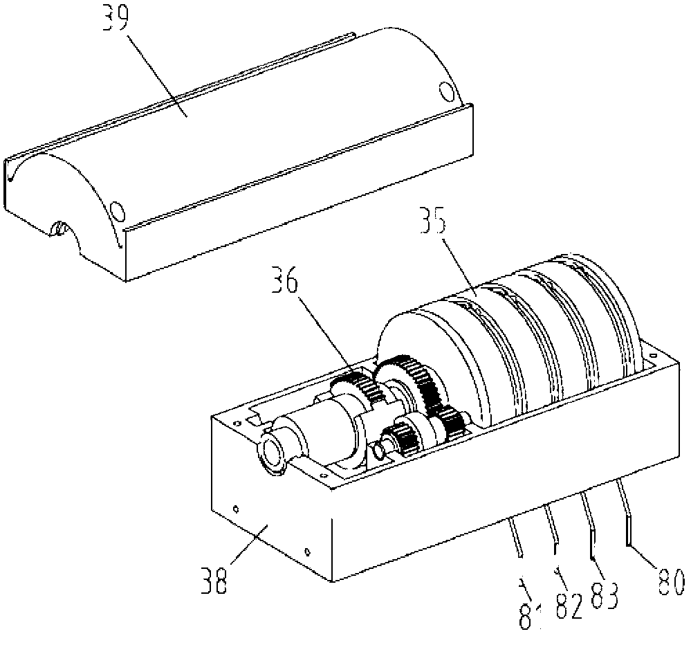
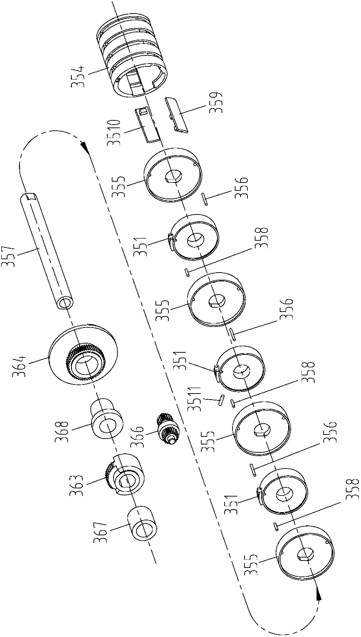
[0143] According to attached Figure 42 , the rotor roller system 3 for variable pitch combined shutters with three louver blades includes a roller mechanism 35 and an incomplete gear turning mechanism 36, and the roller mechanism 35 includes three rotor rollers 351, 352, 353, two Push wheel 355, a rotating shaft 357, a turning cylinder 354, an insert block 359, three short pin shafts 358 and a long pin shaft 356, three rotor scroll wheels 351 and two push wheels 355 are sleeved on the rotating shaft 357 in sequence And installed in the turning cylinder 354, the incomplete gear turning mechanism 36 includes a sleeve 367, a second third gear 363, a second third driven wheel 366, a turning disc sleeve 368 and a turning disc 364, which are axially connected in turn.
[0144] The turning mechanism 36 of the rotor rolling system 3 used for the variable pitch combined shutter with ...
PUM
 Abstract
Description
Claims
Application Information