
A rapid film coating device and method in a laboratory

A coating device and laboratory technology, applied in the field of rapid coating devices in the laboratory, can solve the problems of inability to adapt to rapid coating, occupy a large space, and use a large amount of coating agent, so as to improve efficiency, reduce occupied space, The effect of short coating time

Active Publication Date: 2015-08-19
HARBIN INST OF TECH
View PDF5 Cites 0 Cited by
  • Summary
  • Abstract
  • Description
  • Claims
  • Application Information

AI Technical Summary

Problems solved by technology

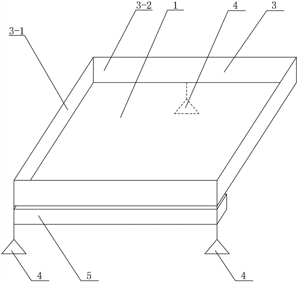
[0003] In order to solve the problem that the existing film coating device occupies a large space, the amount of film coating agent is large, and cannot adapt to the rapid film coating in the laboratory, the present invention further proposes a rapid film coating device and method in the laboratory

Method used


Image

  • A rapid film coating device and method in a laboratory
  • A rapid film coating device and method in a laboratory

Examples


specific Embodiment approach 1

[0013] Specific implementation mode one: combine figure 1 with figure 2 Describe this embodiment, a kind of rapid film coating device in the laboratory described in this embodiment includes a support plate 1, a coating rod 2, a pasting frame 3, a liquid receiving tank 5 and three balance supports 4, and the support plate 1 is horizontally arranged. Paste frame 3 is installed on the upper surface of support plate 1, three balance brackets 4 are arranged on the lower surface of support plate 1 in an equilateral triangle, liquid receiving tank 5 is arranged below support plate 1, and coating rod 2 is used for The paint is dipped from the support plate 1 for coating.

specific Embodiment approach 2

[0014] Specific implementation mode two: combination figure 1 To illustrate this embodiment, the pasting frame 3 of a rapid film coating device in a laboratory described in this embodiment is a rectangular frame composed of two long pasting boards 3-1 and two short pasting boards 3-2.

[0015] The technical effect of this embodiment is: the rectangular frame composed of two long pasting boards 3-1 and two short pasting boards 3-2 can be set and adjusted according to the thickness of the required coating film. Other components and connections are the same as those in the first embodiment.

specific Embodiment approach 3

[0016] Specific implementation mode three: combination figure 1 with figure 2 Illustrate this embodiment, the support plate 1 of a kind of rapid film coating device in the laboratory described in this embodiment is a glass plate or a stainless steel plate, the length of the support plate 1 is 310mm, the width of the support plate 1 is 220mm, and the length of the support plate 1 The thickness is 15mm-20mm.

[0017] The technical effect of this embodiment is: the support plate 1 is made of glass plate or stainless steel plate, so that the support plate 1 is not easily corroded, prolongs the service life of the support plate 1, and avoids the coating film pollution caused by the support plate 1 corrosion. Other components and connections are the same as those in the first embodiment.


PUM

PropertyMeasurementUnit
lengthaaaaaaaaaa
widthaaaaaaaaaa
thicknessaaaaaaaaaa

Abstract

The invention discloses a rapid film coating device and a rapid film coating method in a laboratory, and relates to a film coating device and a film coating method, in particular to a rapid film coating device and a rapid film coating method in a laboratory. The invention aims to solve the problems of large film coating quantity, large scale, high cost and unsuitability for coating a film in the laboratory of an existing film coating device and an existing film coating method. The rapid film coating device comprises a supporting plate, a coating rod, an adhesion frame, a liquid receiving tank and three balancing brackets, wherein the supporting plate is horizontally arranged; the adhesion frame is arranged on the upper surface of the supporting plate; the three balancing brackets are arranged on the lower surface of the supporting plate in an equilateral triangle shape; the liquid receiving tank is formed below the supporting plate; and the coating rod is used for dipping a coating from the supporting plate to carry out film coating. The rapid film coating device and the rapid film coating method are used for rapidly coating a film in the laboratory.

Description

technical field [0001] The invention relates to a film coating device and method, in particular to a rapid film coating device and method in a laboratory. Background technique [0002] At present, in order to solve environmental pollution, there are more and more researches on water treatment membranes and gas membranes, and the problem of laboratory coatings has also arisen from this. Due to the current coating equipment such as coating machines, scrapers, wire rods and other coating equipment, Although the coating effect is good, it is mostly used for large-scale coating. In the laboratory, due to the small amount of coating agent preparation, this coating method causes waste of coating agent and will bring environmental pollution. In addition, the cost of equipment is also relatively high. high. Based on the above, the utility model patent with the publication number CN201470568U and the publication date of May and 19, 2010 discloses an automatic coating and scraping mac...

Claims


Application Information

Patent Timeline
Patent Type & Authority Patents(China)
IPC IPC(8): B05C5/00B05C11/02
Inventor 姜波王慧莲黄玉东刘丽刘巍研战捷祝长城
Owner HARBIN INST OF TECH
Learn More