An anaerobic membrane bioreactor for domestic sewage treatment

An anaerobic membrane biological and anaerobic reaction technology, applied in the field of sewage treatment, can solve the problems of limiting anaerobic membrane bioreactor, fast membrane fouling, short membrane fouling cycle, etc., to improve economic benefits, simple operation, guarantee The effect of water quality

Active Publication Date: 2014-10-01
HARBIN INST OF TECH
View PDF3 Cites 0 Cited by
  • Summary
  • Abstract
  • Description
  • Claims
  • Application Information

AI Technical Summary

Problems solved by technology

[0007] The purpose of the present invention is to solve the problem of fast membrane fouling, short membrane fouling period and high operating cost in existing membrane bioreactors, which limit the application of anaerobic membrane bioreactors

Method used


Image

  • An anaerobic membrane bioreactor for domestic sewage treatment
  • An anaerobic membrane bioreactor for domestic sewage treatment

Examples


specific Embodiment approach 1

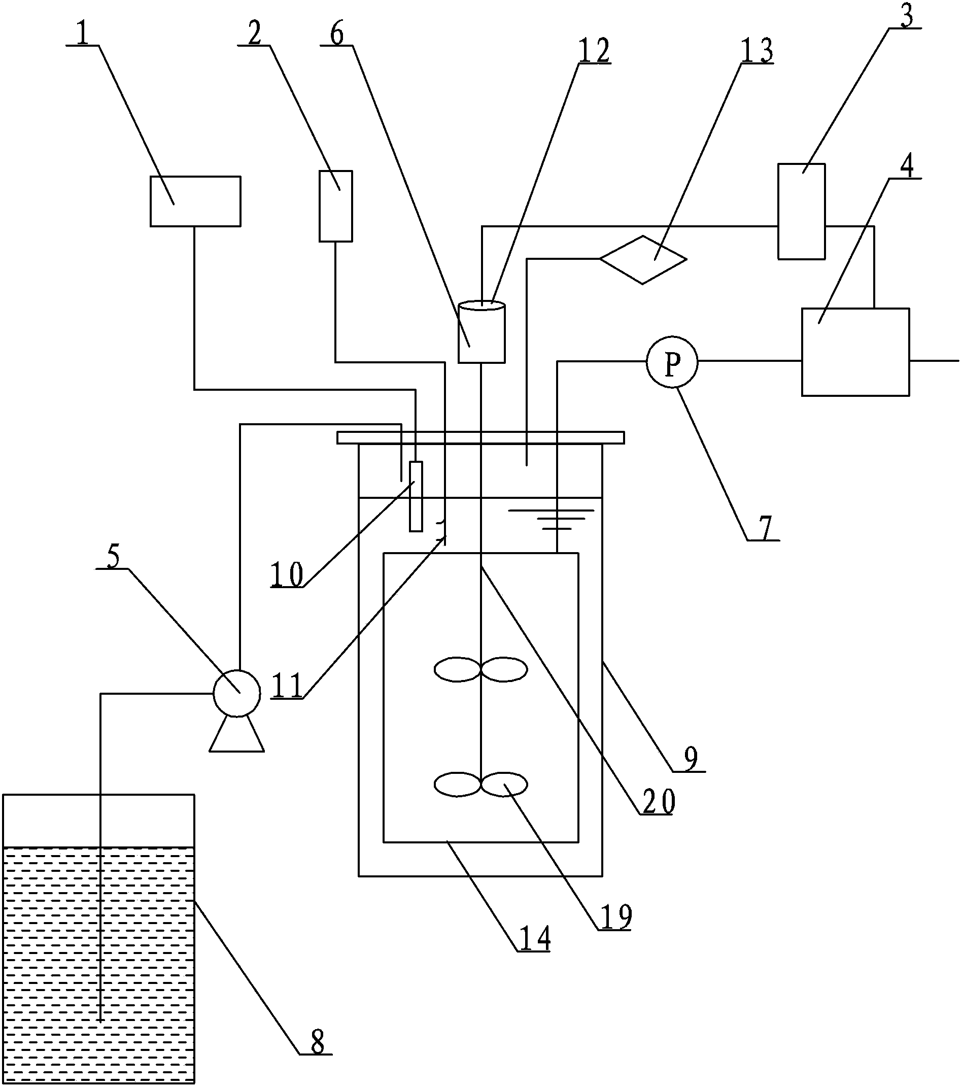
[0016] Specific implementation mode one: combine figure 1 Describe this embodiment, this embodiment comprises temperature controller 1, liquid level relay 2, time relay 3, peristaltic pump 4, water inlet pump 5 and vacuum pressure gauge 7, and described anaerobic membrane bioreactor also includes water inlet tank 8 , anaerobic reaction assembly 9, temperature probe 10, liquid level contact probe 11, stirring device 12, air collection bag 13 and circular membrane assembly 14,

[0017] The circular membrane assembly 14 is arranged in the anaerobic reaction assembly 9, and the water inlet box 8 is arranged on the outside of the anaerobic reaction assembly 9, and the water inlet box 8 is communicated with the water inlet of the anaerobic reaction assembly 9 by a conduit, and the water inlet box 8 is connected to the water inlet of the anaerobic reaction assembly 9. The conduit between the anaerobic reaction components 9 is provided with an inlet pump 5, the peristaltic pump 4 comm...

specific Embodiment approach 2

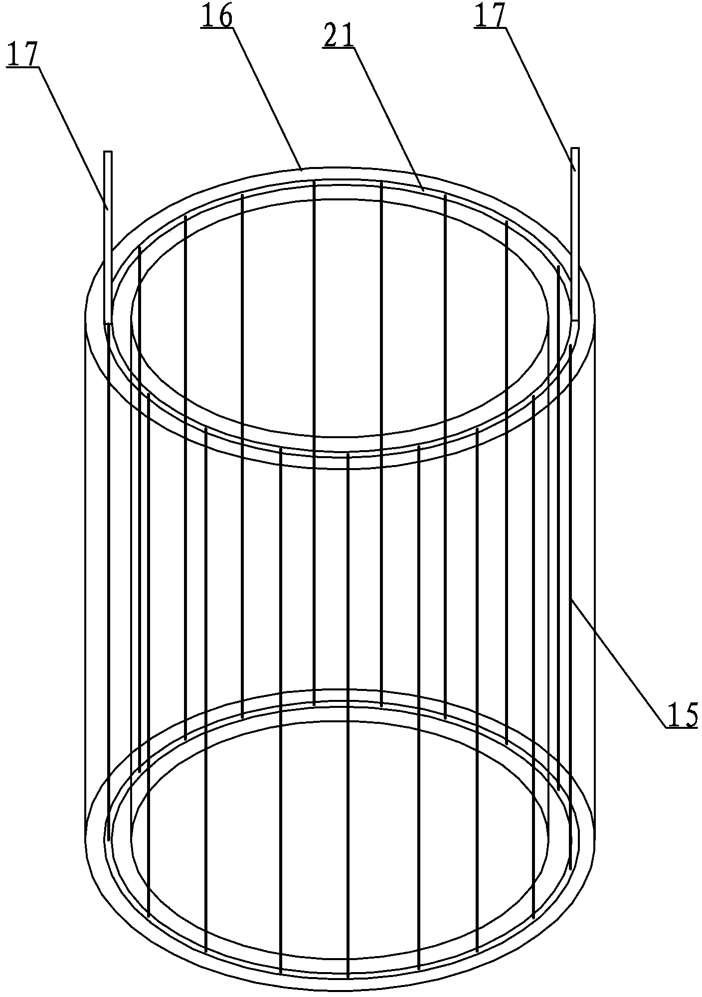
[0024] Specific implementation mode two: combination figure 2 Describe this embodiment, the circular membrane assembly 14 of this embodiment comprises hollow fiber membrane filament 15, water collecting pipe 16 and two water outlet pipes 17, and described water collecting pipe 16 is the circular plexiglass water collecting pipe, and the pipe of water collecting pipe 16 The lower end surface of the wall is provided with a circular slit 21, and the hollow fiber membrane 15 is vertically arranged in the circular slit 21 in a single layer. The two outlet pipes 17 are symmetrically arranged on the upper end surface of the pipe wall of the water collection pipe 16, and the outside of the lower end surface of the water collection pipe 16 is stuck on the protruding hook on the inner wall of the anaerobic reaction assembly 9, so that the entire circular membrane The component 14 is suspended in the cavity of the anaerobic reaction component 9 . Such setting overcomes the problem of u...

specific Embodiment approach 3

[0025] Specific implementation mode three: combination figure 2 To describe this embodiment, the width of the circular slit 21 at the center of the lower end surface of the pipe wall of the water collecting pipe 16 in this embodiment is 2 mm. Such setting satisfies the placement of the hollow fiber membrane filaments 15 . Other compositions and connections are the same as those in the second embodiment.

[0026] Specific implementation mode four: combination figure 1 Describe this embodiment, the stirring device 12 of this embodiment comprises stirring motor 6, double stirring paddle 19 and stirring shaft 20, and the upper end of stirring shaft 20 is connected with the stirring motor 6 that is arranged on anaerobic reaction assembly 9 tops, and the stirring shaft 20 The lower end extends into the inner ring space of the circular membrane module 14 , and the double stirring paddles 19 are arranged on the stirring shaft 20 in the circular membrane module 14 . Such setting me...


PUM

PropertyMeasurementUnit
widthaaaaaaaaaa

Abstract

The invention relates to an anaerobic membrane bioreactor for treatment of domestic sewage, relates to an anaerobic membrane bioreactor, and aims to solve problems that a conventional membrane bioreactor is high in membrane pollution speed, short in membrane pollution period and high in operation cost, and the application of the anaerobic membrane bioreactor is limited. According to the anaerobic membrane bioreactor, a round membrane component is arranged in an anaerobic reaction component, a water inlet tank is communicated with a water inlet of the anaerobic reaction component through a guide pipe, a peristaltic pump is communicated with the round membrane component through a connection guide pipe, and a vacuum pressure gauge is arranged on the guide pipe between the round membrane component and the peristaltic pump; the lower part of a stirring device is arranged in the round membrane component, and a control switch of the stirring device and a control switch of the peristaltic pump are controlled by the same time relay; a gas collecting bag is connected with a gas outlet of the anaerobic reaction component through a guide pipe; and a liquid level contact probe is arranged on a terminal of a liquid level relay, and a temperature probe is arranged on a terminal of a temperature controller. The anaerobic membrane bioreactor is used for treating domestic sewage.

Description

technical field [0001] The invention relates to an anaerobic membrane bioreactor, in particular to an anaerobic membrane bioreactor used for domestic sewage treatment, and belongs to the technical field of sewage treatment. Background technique [0002] Membrane bioreactor is a new sewage treatment process with the most development potential and application prospect developed at the end of the 20th century. It integrates high-efficiency membrane separation and biological treatment technology, and effectively realizes solid-liquid separation. Membrane bioreactor realizes the complete separation of hydraulic retention time and sludge retention time, and has the advantages of high effluent quality standard, stable quality, small footprint, and less residual sludge. [0003] Anaerobic membrane biological reaction technology can not only solve the problems of low anaerobic treatment effect and serious sludge loss, but also use biogas to generate electricity, effectively reducing ...

Claims


Application Information

Patent Timeline
Patent Type & Authority Patents(China)
IPC IPC(8): C02F3/28
Inventor 田禹丁一李之鹏王浩宇吴迪
Owner HARBIN INST OF TECH
Why Eureka
Try Eureka